Overview
Description
[Notes] Renesas Emulator and Flash Memory Programmer Products with a USB Interface Notice Regarding Changes to Windows Driver Policy (PDF | English, 日本語)
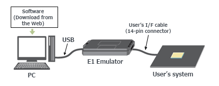
The E1 emulator is an on-chip debugging emulator and flash programmer which supports the major Renesas MCUs. This economical development tool provides basic debugging functionality. Available optional products, such as the hot-plug-in adaptor, allow you to extend debugging functionality or adjust connections.
Successor
| Item | Description |
|---|---|
| For RX or RL78 Family MCU Users | E2 emulator or E2 emulator Lite |
| For RH850 Family MCU Users | E2 emulator |
Note:
- No successors to E1 for V850、78K0R、78K0 or R8C* Family MCU Users.
*E8a emulator supports R8C/3x or R8C/Lx Series MCU.
![E1 emulator [R0E000010KCE00]](https://www.renesas.com/sites/default/files/e1.jpg "E1 emulator [R0E000010KCE00]")
Features
- Affordable yet powerful debugging device that can meet the actual development needs.
Learn more (On-chip Debuggers Performance Property) >> - Enhanced functions for faster debugging
In addition to basic debugging functions, the E1 supports execution time measurement and hot plug-in functionality (dependent on the MCU) that allows connection to the user system while the program is running. - Also functions as an on-board programmer.
Can be used as an on-board programming tool after the debugging, enabling smooth evaluation of the MCU. - Optimally suited for evaluating analogue functions such as A/D and D/A properties.
Electrical characteristics are the same as those of the actual MCU, since the actual MCU is used for debugging. - Serial, JTAG and LPD connections are supported.
For the communication system, serial, JTAG or LPD connection can be selected as required by the type of the target MCU. - Simple connection
Connection requires only a connector mounted on the user system, thus significantly reducing the possibility of loose connection. - Environmentally friendly material
The casing is made of plant-derived polylactide (PLA). - Learn More
Release Information
| Purpose of use | Software to be supported | Target devicesNote1 | Operating Environment |
|---|---|---|---|
| On-chip Debugging | CS+ *Evaluation Software Download | RX, RL78, RH850 [Details] Functions Supported by CS+ (XLSX) (XLSX | English, 日本語) | Operating Environment |
| e² studio *Download | RX, RL78, RH850 [Details] Release notes | ||
| IAR Embedded WorkbenchNote2 | RX, RL78, RH850 | Contact IAR Systems. | |
| Green Hills MultiNote2 | RH850 | Contact Green Hills Software. | |
| iSYSTEM winIDEANote2 | RL78, RH850 | Contact iSYSTEM. | |
| Flash Programming | Renesas Flash Programmer V3 *Evaluation Software Download | RL78, RX, RH850 [Details] List of MCUs supported by Renesas Flash Programmer V3 (PDF | English, 日本語) | Operating Environment |
Notes:
1. For details when using devices of V850 family, 78K0R, 78K0, or R8C family, see E1/E20 software for V850, 78K0R, 78K0, or R8C MCU >>.
2. As for tools produced by partners, contact them directly.
Target Devices
Target Family
- RX Family
- RL78 Family
- RH850 Family
Note: The E1 does not support RH850-family MCUs with the next-generation G4MH core, such as those of the RH850/E2x series. The E2 emulator is available for use with them. - V850 Family
- 78K Family
- R8C Family
Downloads
|
|
|
|
|---|---|---|
| Type | Title | Date |
| Upgrade - IDE | USB Driver for Renesas E-Series V1.01.00
|
|
| Software & Tools - Other | E1, E20 Self-Checking Program V.1.01.00
|
|
| Upgrade - Programmer | External Flash Definition Editor V.1.00 Release 01
|
|
|
3 items
|
||
Documentation
|
|
|
|
|---|---|---|
| Type | Title | Date |
| Manual - Development Tools | PDF 1.53 MB 日本語 | |
| Manual - Development Tools |
PDF
230 KB
日本語
This is a feature list summarizing the capabilities of Renesas' on-chip debuggers for each microcontroller. For the E2 Emulator, E2 Emulator Lite, E1 Emulator, E20 Emulator, MINICUBE2, E10A-USB, and E8a on-chip debuggers, it details the debugging capabilities supported for each corresponding microcontroller, including connection methods, break functions, trace functions, and more.
|
|
| Tool News - Note | PDF 209 KB 日本語 | |
| Application Note |
PDF
1.05 MB
日本語
AI-generated Summary:
The hot plug-in function enables debugging of an RL78 microcontroller during system operation without resetting or modifying the program. It retains failure status, uses ID code authentication for security, and allows RAM monitoring via a dedicated Data Transfer Controller (DTC) without stopping the CPU. Debugging proceeds through Real-time RAM Monitor (RRM) and Dynamic Memory Modification (DMM), accessing RAM, SFRs, and other memory areas. The debugging procedure involves creating a program with hot plug-in initialization, setting build options, programming via Renesas Flash Programmer, connecting with the E1 emulator, and performing debugging.
|
|
| Tool News - Note | PDF 183 KB 日本語 | |
| Tool News - Release | PDF 92 KB 日本語 | |
| Tool News - Release | PDF 83 KB 日本語 | |
| Application Note |
PDF
1.17 MB
日本語
AI-generated Summary:
Main-core debugging enables secure development by separating secure programs running on the ICU-M core from non-secure programs on the main CPU core. It allows debugging of non-secure user programs while keeping secure information confidential. The method uses the E1/E20/E2/IE850A emulator and requires specific system configurations and authentication procedures. Key terminology includes integrated development environment, emulator debugger, host machine, target device, and user system. Manuals for the emulator provide hardware specifications, connection details, and usage notes essential for effective debugging.
|
|
| Application Note |
PDF
1.17 MB
日本語
AI-generated Summary:
Debugging methods focus on devices with an initially stopped CPU core and those transitioning to standby modes to optimize power consumption. Key capabilities include verifying core activation, measuring execution times for core activation and standby transitions, and restarting debugging at critical points such as core activation or MCU wake-up. Supported devices include various RH850 series MCUs. The document details environment setup, debugging configurations in CS+ and MULTI IDEs, and specific debugging techniques for different standby modes. It also covers precautions and terminology related to debugging and device operation.
|
|
| Tool News - Note | PDF 243 KB 日本語 | |
| Tool News - Note | PDF 150 KB 日本語 | |
| Tool News - Note | PDF 147 KB 日本語 | |
| Tool News - Note | PDF 159 KB 日本語 | |
| Tool News - Note | PDF 92 KB 日本語 | |
| Tool News - Note | PDF 127 KB 日本語 | |
| Manual - Development Tools | PDF 954 KB | |
| Manual - Development Tools | PDF 1.12 MB | |
| Manual - Development Tools | PDF 1.07 MB | |
| Manual - Development Tools | PDF 821 KB | |
| Tool News - Note | PDF 168 KB 日本語 | |
| Application Note |
PDF
792 KB
日本語
AI-generated Summary:
This document details the hardware and software configuration for controlling a brushless DC motor using the RL78/F14 microcontroller with 120-degree conduction control and Hall sensor inputs. It describes the hardware setup including terminal interfaces for Hall sensors, PWM outputs, error detection inputs, and bus voltage measurement. Peripheral functions such as external interrupts, timers, and A/D converters are explained. The software structure includes specific header and source files for motor control, sensor handling, board interface, and initialization routines.
|
|
| Application Note |
PDF
790 KB
日本語
AI-generated Summary:
The RL78/F14 microcontroller controls a sensorless vector permanent magnetic synchronous motor using a detailed hardware configuration. It includes A/D converters for phase current and bus voltage measurements, complementary PWM outputs for inverter control, and error detection inputs. Peripheral functions include a 10-bit A/D converter, a 1 ms interval timer, complementary PWM output with dead time, and overcurrent detection that sets PWM outputs to high impedance.
|
|
| Application Note |
PDF
837 KB
日本語
AI-generated Summary:
The document details the hardware and software configuration for sensorless 120-degree conduction control of a brushless DC motor using the RL78/F14 microcontroller. It describes the hardware setup, including voltage measurement terminals, PWM outputs, error detection inputs, and peripheral functions like A/D converters and timers. The software structure outlines the file organization for motor control, including headers and source files for board-specific and sensorless control functions.
|
|
| Application Note |
PDF
822 KB
日本語
AI-generated Summary:
The document details the hardware and software configuration for sensorless 120-degree conduction control of a brushless DC motor using the RL78/F14 microcontroller. It outlines the hardware setup including the RL78F14 MCU, power, inverter circuits, and terminal interfaces for PWM outputs and comparator inputs. Peripheral functions like AD conversion, timer units, and error detection are specified. The software structure includes header and source files managing motor control, board-specific processing, and sensorless control algorithms.
|
|
| Manual - Development Tools | PDF 683 KB 日本語 | |
| Manual - Development Tools | PDF 327 KB 日本語 | |
| Manual - Development Tools | PDF 1.73 MB 日本語 | |
| Manual - Development Tools | PDF 284 KB 日本語 | |
| Guide | PDF 3.29 MB 日本語 | |
| Guide | PDF 3.36 MB 日本語 | |
| Application Note |
PDF
573 KB
日本語
AI-generated Summary:
The guide addresses common startup issues with the E1/E20 On-Chip Debugging Emulator. It explains warning messages about project file restoration due to version mismatches in CubeSuite+ and advises upgrading to the latest version. It highlights errors caused by missing CC-RX compiler installations and instructs users to install the compiler. The guide also details handling version differences in the CC-RX compiler, allowing debugging to continue if compatible or requiring version adjustments via the property panel.
|
|
| Guide | PDF 2.00 MB 日本語 | |
| Manual - Development Tools | PDF 178 KB 日本語 | |
| Manual - Development Tools | PDF 153 KB 日本語 | |
| Application Note |
PDF
525 KB
日本語
AI-generated Summary:
The External Flash Definition Editor (EFE) enables creation of custom write programs for flash memory devices with unsupported command sets. Users customize sample C source programs, link header and library files, then create RFD and USD files for use with emulator software. The custom program must not exceed 8,192 bytes in memory size and 256 bytes in stack size. The development environment requires specific sample files, a suitable C/C++ compiler, and emulator tools.
|
|
| Manual - Development Tools | PDF 140 KB 日本語 | |
| Tool News - Release | PDF 309 KB | |
|
37 items
|
||
Design & Development
Sample Code
Sample Code
Filters
|
||
|---|---|---|
| Type | Title | Date Date |
| Sample Code | Motor control by RL78/F14 micro controller 120 degrees conducting control of brushless DC motor with hall sensor Rev.1.00 - Sample Code
|
|
| Sample Code | Motor control by RL78/F14 micro controller Sensorless vector control of permanent magnetic synchronous motor Rev.1.00 - Sample Code
|
|
| Sample Code | Motor control by RL78/F14 micro controller sensorless 120 degrees conducting control of brushless DC motor (A/D) Rev.1.00 - Sample Code
|
|
| Sample Code | Motor control by RL78/F14 micro controller sensorless 120 degrees conducting control of brushless DC motor (COMP) Rev.1.00 - Sample Code
|
|
4 items
|
||
Additional Details
Specifications
Note that some functions shown here may not be supported under the IDE you use. Performance property and Connection system also vary depending on the MCU type.
| Item | Description |
|---|---|
| See On-Chip Debugger Functional Overview (PDF | English, 日本語). |
| On-board programming | Supported |
| User interface | 14-way cable [7614-6002 (product of 3M Co., Ltd.) and 2514-6002 (product of 3M Limited)] |
| PC Interface | USB 2.0, full speed and high speed |
| Target board connection | Via attached user I/F cable (Connection signals vary by the target MCU type.) |
| Operating voltage range | 1.8V to 5.5V (depends on the target MCU) |
| Power supply from Emulator | Supply current: Up to 200mA, Supply voltage: 3.3V or 5V |
| External dimension (Except the protruding parts) | 109.4 mm×53.2 mm×18.6 mm |
| Conformance with overseas standards | European Standards: EN 55022 Class A, EN 55024 US FCC Standard: FCC part 15 Class A |
Components
- E1 Emulator main unit
- USB cable
- User's system I/F cable
- Software CD-ROM
- Installation guide
- Self-Checking Program
- USB driver
- E1/E20 Emulator User's Manual
System Configuration
Optional Products
Following optional products are provided to facilitate the use of the E1 emulators. Please make sure to choose the products that match MCUs you use.
Conversion Adapter
Converts the number and pitch of the pins in the connector for the connection with the emulator.
| MCUs | ||||||
|---|---|---|---|---|---|---|
| RX | RL78 | RH850 | V850 | 78K | R8C | |
| 14-Pin to 38-Pin Conversion Adapter for the E1 Emulator R0E000010CKZ00 R0E000010CKZ00 User's Manual (14-Pin to 38-Pin Conversion Adapter for E1 Emulator) (PDF | English, 日本語) An adapter for converting the 14-pin/2.54-mm pitch connector on the head of the emulator user interface cable to a 38-pin/0.5-mm pitch connector | lens | — | — | — | — | — |
| 38-Pin Conversion Adapter for the E1 Emulator QB-F14T38V850-01 QB-F14T38V850-01 ユーザーズ・マニュアル (E1エミュレータ用14ピン/38ピン変換アダプタ) / QB-F14T38V850-01 User's Manual (14-Pin to 38-Pin Conversion Adapter for E1 Emulator) (PDF) An adapter for changing to a 14-pin user interface for connection to a Mictor connector mounted on a V850-based target system | — | — | — | lens | — | — |
| Small Connector Conversion Adapter for the E1 Emulator R0E000010CKZ11 R0E000010CKZ11 User's Manual (Small Connector Conversion Adapter for E1 Emulator) (PDF | English, 日本語) An adapter for converting the 14-pin/2.54-mm pitch connector on the head of the emulator user interface cable to a 14-pin/1.27-mm pitch connector | lens | lens | lens | lens | lens | lens |
| 14-Pin to 16-Pin Conversion Adapter for the E1 Emulator QB-F14T16-01 QB-F14T16-01 ユーザーズマニュアル(E1エミュレータ用14ピン/16ピン変換アダプタ) / QB-F14T16-01 User's Manual (14-Pin to 16-Pin Conversion Adapter for E1 Emulator) (PDF) An adapter for changing the 14-pin/2.54-mm pitch connector on the head of the E1 emulator user interface cable to a MINICUBE2-compliant 16-pin/2.54-mm pitch connector | — | — | — | lens | lens | — |
lens Available | — Not Available
Hot-plug Adapter
Allows you to connect the emulator without having to turn off the system (Hot Plugin).
| MCUs | ||||||
|---|---|---|---|---|---|---|
| RX | RL78 | RH850 | V850 | 78K | R8C | |
| Hot-plug Adapter for the E1 Emulator R0E000010ACB00 R0E000010ACB00 User's Manual (Hot-plug Adapter for E1 Emulator) Rev.1.01 (PDF | English, 日本語) An adapter that allows connection of an emulator to a running user system without turning the power off | lens Note1 | lens Note1 | lens Note1 | lens Note1 | — | — |
lens Available | — Not Available
Note:
- Refer to On-Chip Debugger Functional Overview (PDF | English, 日本語) for the applicable MCU groups.
Isolator
Enables debugging in an environment where there is a difference in potential between the user system GND and the host PC GND.
| MCUs | ||||||
|---|---|---|---|---|---|---|
| RX | RL78 | RH850 | V850 | 78K | R8C | |
| Isolator for the E1 Emulator R0E000010ACB10 R0E000010ACB10 User's Manual (Isolator for E1 Emulator) (PDF | English, 日本語) (For the RX or the R8C family) | lens | — | — | — | — | lens |
| Isolator for the E1 Emulator R0E000010ACB20 R0E000010ACB20 User's Manual (Isolator for E1 Emulator) (PDF | English, 日本語) (For the RL78 or the RH850 family) | — | lens | lens | — | — | — |
lens Available | — Not Available
Low voltage OCD Board
Enables you to debug the target MCU, even if the adapter voltage is not high enough to reprogram internal Flash ROM. This product is used between the emulator and a user's system, and is united by the in-circuit connection with the user's system.
| MCUs | |
|---|---|
| RL78/G10 | |
| Low voltage OCD Board for RL78/G10 (10-pin/16-pin) R0E510Y47LVB00 Low voltage OCD Board for RL78/G10 (10pin, 16pin) Rev.1.00 (PDF | English, 日本語) An OCD board for debugging an RL78/G10 MCU (10-pin or 16-pin) with an adapter voltage below 4.5 V | lens |
lens Available | — Not Available
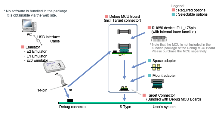
Debug MCU Board
Enables the in-circuit connection of the emulator with the user's system. This board allows you to use enhanced debugging functions. The applicable debugging function varies depending on the MCU type.
| MCUs | |
|---|---|
| RH850 | |
Debug MCU Board for RH850 Note: The package of the Debug MCU Board does not include the MCU. Please purchase it separately. For details, contact either a Renesas Electronics Corporation representative (responsible for sales) or distributor. | lens |
lens Available | — Not Available
System configuration
Design Support
E1 emulator [R0E000010KCE00] Information for Users
Information on the discontinuation of E1 emulator production and on its successor products
We have already discontinued production of the E1 emulator due to components of the product having reached their EOL (end of life, i.e. end of production). Please click on the following link to confirm the details and our successor products.
>> Tool News: [Notification] End of Life (EOL) Notice for E1 Emulator (PDF | English, 日本語)
Support
Support Communities
- An “A timeout error has occurred in emulator firmware processing (E1815001)” error occurs when programming an RX72M (100-pin) using FINE.
When using an RX72M (100-pin) and programming the microcontroller via FINE, the error “A timeout error has occurred in emulator firmware processing. (E1815001)” occurs. Current microcontroller schematic connections: 1.Pull-up (pulling high) pins: MD/FINED, RESn 2.Pull-down (pulling low) pins: XCIN, EMLE, NMI
Dec 21, 2025 - unable to connect emulater, Loading 'exrh850g3.dll' failed with 0x0
When I connect my P1MC with E2 (S/N: 2CS010559D), it shows bellow error ,how can I fix it.
Mar 20, 2025 - LPD Connection failed in RH850 but flashing through RFP
... Please check the LPD connection settings.(E1203240) And i have attached Debug tool setting FYR. So I do iterations to resolve the problem 1) Change Emulator E1with same system and its flashed and worked successfully (emulator spared) 2) I check with RFP, with the problem emulator E1 and Check its ...
Nov 23, 2023
Knowledge Base
- Unable to debug or write using the E2 Emulator (E2, E2 Lite, E1)
Check the switch of the 20-pin (1.27-mm pitch)/14-pin (2.54-mm pitch) connector conversion adapter. When using RH850, RX, set the switch to“1”. When using RL78, set the switch to “3”.
Mar 8, 2021 - There are two reset lines of RL78 microcontrollers w/ E1 or E20 emulator (E2, E2 Lite, E1, E20) [RL78]
... RL78 family microcontroller, the reset signal from the target system is temporarily masked by the E1 or E20 emulator, after which the E1 or E20 emulator transmits the RESET signal to the microcontroller (that is, the RESET pin needs to be controlled from the E1 or E20 emulator). On the ...
Mar 5, 2021 - Programming Multiple Devices Using Renesas Flash Programmer (RFP) and E1 Emulator/E2/E2 Lite (E2, E2 Lite, E1)
... option when starting the RFP via command.For versions earlier than RFP V3.05.00, which do not have tool option feature, create a project separately for each E1 emulator/E2/E2 Lite with the serial number specified, and specify each project when starting the RFP via command.
Mar 4, 2021

Support Communities


