Features
- CPU Core:
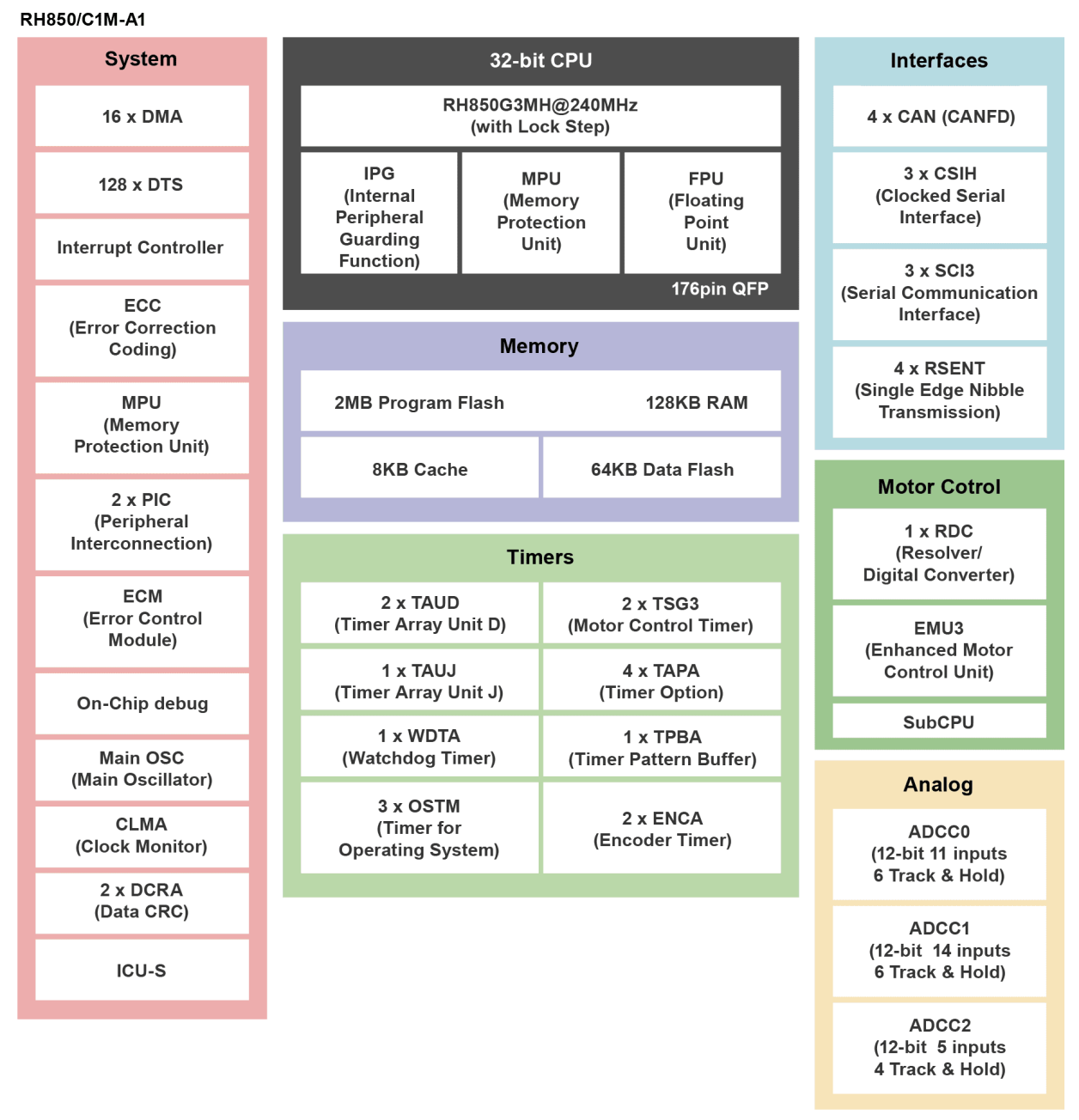
- C1M-A1: 240MHz core (Inc. Lockstep dual core x1)
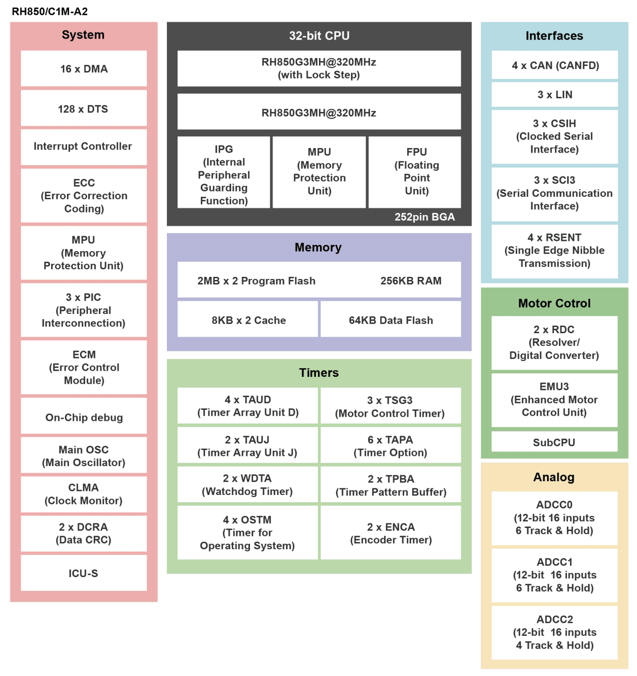
- C1M-A2: 320MHz core x2 (Inc. Lockstep dual core x1)
- FPU
- Clock:
- Main Oscillator: 20 MHz
- PLL with selectable SSCG mode: 240 or 320 MHz
- PLL without SSCG mode: 80 MHz
- On-chip low-speed oscillator: 240 kHz
- Data transfer: DMAC / DTS
- Timer:
- Timer array unit D (TAUD) 2 or 4 units
- Timer array unit J (TAUJ) 1 or 2 units
- Motor control timer (TSG3) 2 or 3 units
- Encoder timer (ENCA) 2 units
- Analog: SAR A/D Converter 30 or 48ch, 3 units
- Communication Interfaces:
- Clocked Serial Interface H (CSIH) 3 channels
- CAN interface(RS-CANFD) 4 channels
- LIN interface(RLIN3) 3 channels
- Serial Communication Interface (SCI3) 3 channels
- RSENT 4 channel
- Motor Control:
- Motor control timer (TSG3) 2 or 3 units
- R/D converter (RDC3A) 1 or 2 units
- Enhanced motor control unit (EMU3) 1 unit
- Safety:
- Multi-Input Signature Generator (MISG)
- Clock Monitor
- Watchdog Timer
- Secure Watchdog Timer
- Memory protection function
- Power Supply Voltage:
- 1.15 - 1.35 V (CPU core)
- 4.5 - 5.5 V (I/O, System, AD converter, RD converter)
- Temperature: Tj= -40 - +150°
Description
The RH850/C1M-Ax ASIL-C microcontroller is equipped with an RH850 Family G3MH CPU core, which operates at a frequency of 1x 240MHz for C1M-A1 and 2x 320MHz for C1M-A2, providing high processing power. Along with the ROM, RAM and DMA, it includes various timers such as a motor control timer, various serial interfaces including CAN (CAN FD compatible), a 12-bit A/D converter (ADC), an R/D converter (RDC3A) that converts position-sensor output signals into digital angle data and a parallel embedded motor control unit (EMU3), providing a peripheral function set that is ideal for motor control in HEV/EV traction-inverter applications. In addition, C1M-A2 can simultaneously control two motors, e.g. for a starter/generator system.
Parameters
| Attributes | Value |
|---|---|
| Main CPU | G3MH |
| Program Memory (KB) | 2048, 4096 |
| RAM (KB) | 128, 256 |
| Supply Voltage (V) | 4.5 - 5.5 |
| I/O Ports | 81, 99 |
| DRAM I/F | No |
| 3D GPU | No |
| Temp. Range (°C) | -40 to +150 |
| Ethernet speed | No |
| Ethernet (ch) | 0 |
| EtherCat (ch) (#) | 0 |
| USB FS (host ch/device ch) | ( 0 / 0 ) |
| USB HS (host ch/device ch) | ( 0 / 0 ) |
| USB SS (host ch/device ch) | ( 0 / 0 ) |
| PCI Express (generation and ch) | No |
| SCI or UART (ch) | 4 |
| SPI (ch) | 3 |
| CAN (ch) | 0 |
| CAN-FD (ch) | 4 |
| Wireless | No |
| SDHI (ch) | 0 |
| PWM Output (pin#) | 0 |
| 32-Bit Timer (ch) | 4, 8 |
| 16-Bit Timer (ch) (#) | 32, 64 |
| 8-Bit Timer (ch) | 0 |
| Standby operable timer | No |
| Asynchronous General Purpose Timer / Interval Timer (ch) | 0 |
| 16-Bit A/D Converter (ch) | 0 |
| 14-Bit A/D Converter (ch) | 0 |
| 12-Bit A/D Converter (ch) | 30, 48 |
| 10-Bit A/D Converter (ch) | 0 |
| 24-Bit Sigma-Delta A/D Converter (ch) | 0 |
| 16-Bit D/A Converter (ch) | 0 |
| 12-Bit D/A Converter (ch) | 0 |
| 10-Bit D/A Converter (ch) (#) | 0 |
| 8-Bit D/A Converter (ch) | 0 |
| Capacitive Touch Sensing Unit (ch) | 0 |
| Graphics LCD Controller | No |
| MIPI Interfaces (CSI) (ch) | 0 |
| Image Codec | No |
| Segment LCD Controller | No |
| Security & Encryption | Yes |
Application Block Diagrams
 | xEV Inverter with Inductive Position Sensor (IPS) This cost-efficient xEV inverter system with IPS offers high accuracy, noise immunity, and reduced BOM. |
 | Motor Generator System High-performance xEV motor control design with ASIL C support, lock-step CPUs, and reduced BOM cost. |
 | Automotive Monitoring Function Extension Compact CMIC-based system for integrating motor monitoring and protection functions in automotive systems. |
 | Low Voltage Inverter for 2/3 Wheeler Traction Motor Control Inverter for 2/3 wheelers using automotive MCUs and analog products, designed for motor control. |
 | xEV Inverter Compact, efficient xEV inverter design with advanced calibration tools and proven 100kW motor performance. |
Applied Filters:


