特長
- 広い入力電圧範囲:2.5V〜20V
- 最大出力電流:500mA
- 低ドロップアウト電圧:500mA時269mV(typ.)
- 低GND電流
- 出力電圧調整可能:1.224V〜18V
- 優れたラインおよび負荷レギュレーション
- 出力コンデンサに1μF〜200μFのMLCCを使用することで安定
- フォールドバック付短絡電流制限回路
- 過熱防止シャットダウン機能
- 8 Ld DFN(3mm×3mm)およびSOICパッケージ

説明
RAA214250は、2.5V~20Vで動作し、269mVの標準的なドロップアウトで最大500mAの出力電流を提供する低ドロップアウトのリニア電圧レギュレータです。 出力電圧は、外付けのフィードバック抵抗で1.224Vから18Vまで調整可能です。
パラメータ
| 属性 | 値 |
|---|---|
| Input Voltage (Min) (V) | 2.5 |
| Input Voltage (Max) (V) | 20 |
| Output Voltage (Min) (V) | 1.22 |
| Output Voltage (Max) (V) | 18 |
| Output Current 1 (Max) (A) | 0.5 |
| Drop Out Voltage (Typical) | 0.27 |
| Fixed Output Voltage Option | No |
| PSRR (db) | 87 |
| Quiescent Current | 68 µA |
| Noise (10Hz to 100kHz) (μVrms) | 167 |
| Qualification Level | Standard |
アプリケーション・ブロック図
 | ヒューマノイド用バッテリマネジメントシステム 安全なリアルタイムの電力管理、保護機能、およびバッテリ状態制御を実現する、ヒューマノイドロボット向け統合BMS。 |
 | 3.7kWシングルマトリックスコンバータ BDS GaNデバイスと高周波トランスを採用した高効率シングルAC/DCマトリックスコンバータで、コンパクトかつ高出力の動作を実現します。 |
 | スマート街灯 センサによる照度制御、リアルタイムのデータ共有、遠隔管理機能を備えたネットワーク接続型IoT街灯で、より安全でエネルギ効率の高い都市の実現に貢献します。 |
 | シングルステージDAB方式ソーラーマイクロインバータ 本システムは、GaN (窒化ガリウム) ベースのマイクロインバータにより、500Wの高密度かつ高効率な電力を供給します |
 | 3.6kW Vienna整流器 低THD、ほぼ1の力率、および安定化DCバスを備えた高効率AC/DC変換用、3.6kW 3相GaNベースのVienna整流器。 |
 | ピラニ真空計 熱伝導率を利用して真空圧を測定するシステムで、高精度でコンパクトな設計。 |
 | ハイブリッドインバータ このハイブリッドインバータシステムは、ハイブリッド構成とMPPTアルゴリズムによって効率的な蓄電を可能にします。 |
 | スマートタッチパネル 低消費電力MCUを搭載したスマートタッチパネルは、リアルタイムでの空気質や温度の表示とタッチ操作を可能にします。 |
 | GNSSによる通行料自動徴収 ETCシステムは料金支払いを自動化することで、交通量を減らし、手作業による料金所の渋滞をなくします。 |
 | スマート水槽 このスマート水槽は水の交換を自動化し、Wi-Fiベースのモバイルアプリで制御できます。 |
 | スマートゆりかご 鳴き声検出、リアルタイムアラート、自動スイング機能、Bluetoothモバイルアプリのサポートを備えたスマートゆりかご。 |
 | レベル2 EV充電器 効率的なEV充電と管理のための高度な接続性を備えたモジュラEVSEシステム。 |
 | 48V/3kW 2/3 輪車用モータ制御 48V/3kWのモータ制御システムは、スケーラブルなインバータ設計、位相過電流障害検出、ASIL-B安全性を特長としています。 |
 | 太陽光発電(PV)アーク検出システム リアルタイムのPVアーク検出システムは、迅速かつ正確な障害の特定により、火災のリスクを最小限に抑えます。 |
 | LVDTによる変位測定 産業オートメーション向けの堅牢な信号処理を備えた高精度 LVDT 変位センサシステム。 |
このデバイスに組み合わせたい製品
更に設計開発を進めるための製品を探してみましょう
Renesas Boards & Kits

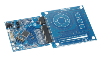
LDO Linear Regulator Evaluation Board with 2.5V to 20V Vin Range, Adjustable 3.3V 500mA Output
The RTKA214250DE0020BU evaluation board provides a simple platform to evaluate the 3×3mm 8 Ld DFN and SOIC version of the RAA214250 on the same board.

双方向デジタル電源評価キット
CN028-BIDIRDPSEVZ評価キットは、CN028-BIDIRDPSPFCEVZボードとCN028-BIDIRDPSDABEVZボードを組み合わせて、高性能の双方向電力変換を実現します。 CN028-BIDIRDPSPFCEVZボードは、デジタル制御とトーテムポールブリッジレスPFCトポロジを採用した3.6kWのAC/DC電源で、高いスイッチング周波数で効率的な連続導通モード動作を可能にします。 CN028-BIDIRDPSDABEVZボードは、デュアルアクティブブリッジと高度なトリプル位相シフト制御を備えた3.6kWの絶縁型DC/DC電源で、ソフトスイッチング、高効率... 続きを読む
RL78/F25搭載静電容量タッチ評価システム
RL78/F25搭載静電容量タッチ評価システム(RSSK-RL78F25)は、ルネサスが提供するタッチキー・ソリューションを容易に評価することができるキットです。 キットに含まれるボードやソフトウェアを用いて、キット購入後すぐに評価を始めることができます。

RL78/F22搭載静電容量タッチ評価システム
RL78/F22搭載静電容量タッチ評価システム(RSSK-RL78F22)は、ルネサスが提供するタッチキー・ソリューションを容易に評価することができるキットです。キットに含まれるボードやソフトウェアを用いて、キット購入後すぐに評価を始めることができます。本キットでは自己容量方式のボタンおよびスライダー電極の評価ができます。

USB-UART、USB-I2C、USB-I3Cデモンストレーションボード用ユニバーサルUSBコンバータ
QCIOT-USB2SERDEMOZボードは、UART、SPI、I2C、およびI3Cを組み込んだUSB-シリアルコンバータであり、シンプルな端末インタフェースを使用してPC経由でデバイスと通信するために、必要なシリアル通信プロトコルに柔軟に接続できます。 トランスペアレントモードに加えて、UART-USBチャネルはATコマンドインタフェースをサポートしており、サポートされているシリアル通信プロトコルを使用してセンサの接続ステータスを照会できます。
QCIOT-USB2SERDEMOZは、複数の一般的なシリアル通信プロトコルをサポートするオールインワンボードソリューションであり... 続きを読む

IEEE 1588 ソリューションのリファレンスデザイン
このIEEE 1588ソリューションは、マスターとスレーブの間で最大50ns未満のクロック同期を実現し、5Gネットワークの正確な同期信号を再構築します。
IEEE 1588 は、コンピュータ ネットワーク内のクロックを同期するために使用される PTP (Precision Time Protocol) システムです。 ローカルエリアネットワークでは、サブマイクロ秒の範囲でクロック精度を制御できるため、計測・制御システムに適しています。 5Gの到来に伴い、大規模なネットワーク同期を必要とする基地局やIoTデバイスが大量に存在します。 ルネサスの 8A34002 同期タイミングデバイスは... 続きを読む
このボードをリモートでテストする
アブソリュートインダクティブポジションセンサのリファレンスデザイン
CN317-ABSIPSPOCZ アブソリュートインダクティブポジションセンサのリファレンスデザインは、2 つの誘導型ポジションセンサ (IPS2200) とコスト効率の高いマイクロコントローラ (RX24T) を組み合わせて、シンプルなロータリエンコーダの機能を実現したボードです。 RX24Tは、2つのIPS2200からの微分サインとコサインの出力を測定し、それらを絶対位置に変換して、結果を出力に提供する役割を果たします。 より軽く、より薄く、より柔軟な設計、優れた性能、および完全な浮遊磁場耐性という利点があります。
このボードをリモートでテストする
レベル2 EV充電器リファレンスデザイン
本モジュール式EV充電設備(EVSE)システムは、スマートEV充電器の開発を容易にし、市場投入を加速します。 ルネサスのコントローラボードはパワーボード上にスタックして搭載でき、最大22kWまでの単相~三相まで柔軟な充電構成に対応します。 Wi-Fi、Bluetooth® Low Energy(LE)、NFCに加え、オプションでEthernetにも対応し、多様な接続ニーズに応えます。 高耐圧AC/DCを採用することで、フォトカプラを不要とし、システム構成を簡素化します。 デュアルバンクフラッシュ対応MCUにより... 続きを読む


