
特長
- AEC-Q100準拠
- 動作電源電圧範囲:3V~32V
- 入力オフセット電圧(VIO):最大±1.2mV
- 入力オフセット電圧温度ドリフト:±1µV/℃(標準)
- 利得帯域幅積(GBW):5MHz(標準)
- スルーレート:8.5V/µs(標準)
- 最大1000pFの容量性負荷で安定動作
- 位相補償回路内蔵
- 出力短絡保護回路内蔵
- 動作周囲温度範囲:−40℃~+125℃
説明
REAC844Aは、AEC-Q100準拠の車載向けクワッドバイポーラ入力オペアンプです。周囲温度−40℃~+125℃の範囲で、入力オフセット電圧(VIO)最大±1.2mVを実現します。 また、容量性負荷に対する優れた安定性を備え、クロスオーバー歪みを発生しません。 さらに、8.5V/µsのスルーレートにより優れた応答性能を実現し、マルチチャネルのセンサ信号処理やモータ制御用途に適しています。
パラメータ
| 属性 | 値 |
|---|---|
| Channels (#) | 4 |
| Temp. Range (°C) | -40 to +125 |
| Bandwidth (MHz) | 5 |
| Gain Min | 25000 |
| Offset Voltage (Max) (mV) | 1.2 |
| IBIAS (nA) | 6 |
| IOUT (A) | 0.02 |
| CMRR (dB) | 100 |
| Rail-to-Rail Input | No |
| Rail-to-Rail Output | No |
| Common Mode Input Voltage Range (V) | 3-32 |
| Output Voltage Swing Range (V) | VOL1+13.7(Min.)-13.7(Max), VOL2+13.5(Min.)-13.5(Max) |
| IS per Amp (mA) | 1.5 |
| Single Supply Voltage Range (V) | 3 - 32 |
| Slew Rate (V/µs) | 8.5 |
| VS (Min) (V) | 3 |
| VS (Max) (V) | 32 |
| Dual Supply Range (V) | V+-1.5(Min.), V+-16(Max.) |
| Input Offset Voltage Vio (Max) (mV (±)) | 1.2 |
| Supply Current Icc/Idd (Max) (mA) | 5.5 |
| Qualification Level | Automotive(AEC-Q100 Compliant) |
| Simulation Model Available | SPICE |
パッケージオプション
| Pkg. Type | Pkg. Dimensions (mm) | Lead Count (#) | Pitch (mm) |
|---|---|---|---|
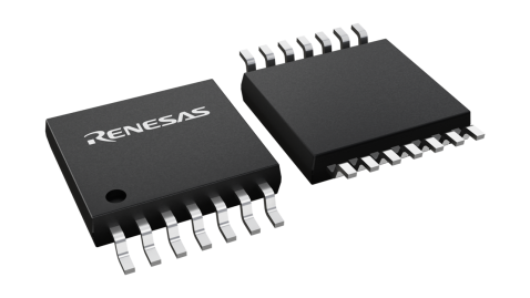
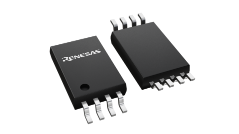
| TSSOP | 5 x 4.4 x 1.2 | 14 | 0.65 |
製品比較

アプリケーション・ブロック図
 | 1.2kW高電圧GaN FET搭載インバータ 産業用モータドライブ用のGaNベースのPFCを備えた効率的な高電圧GaN FET搭載インバータ。 |
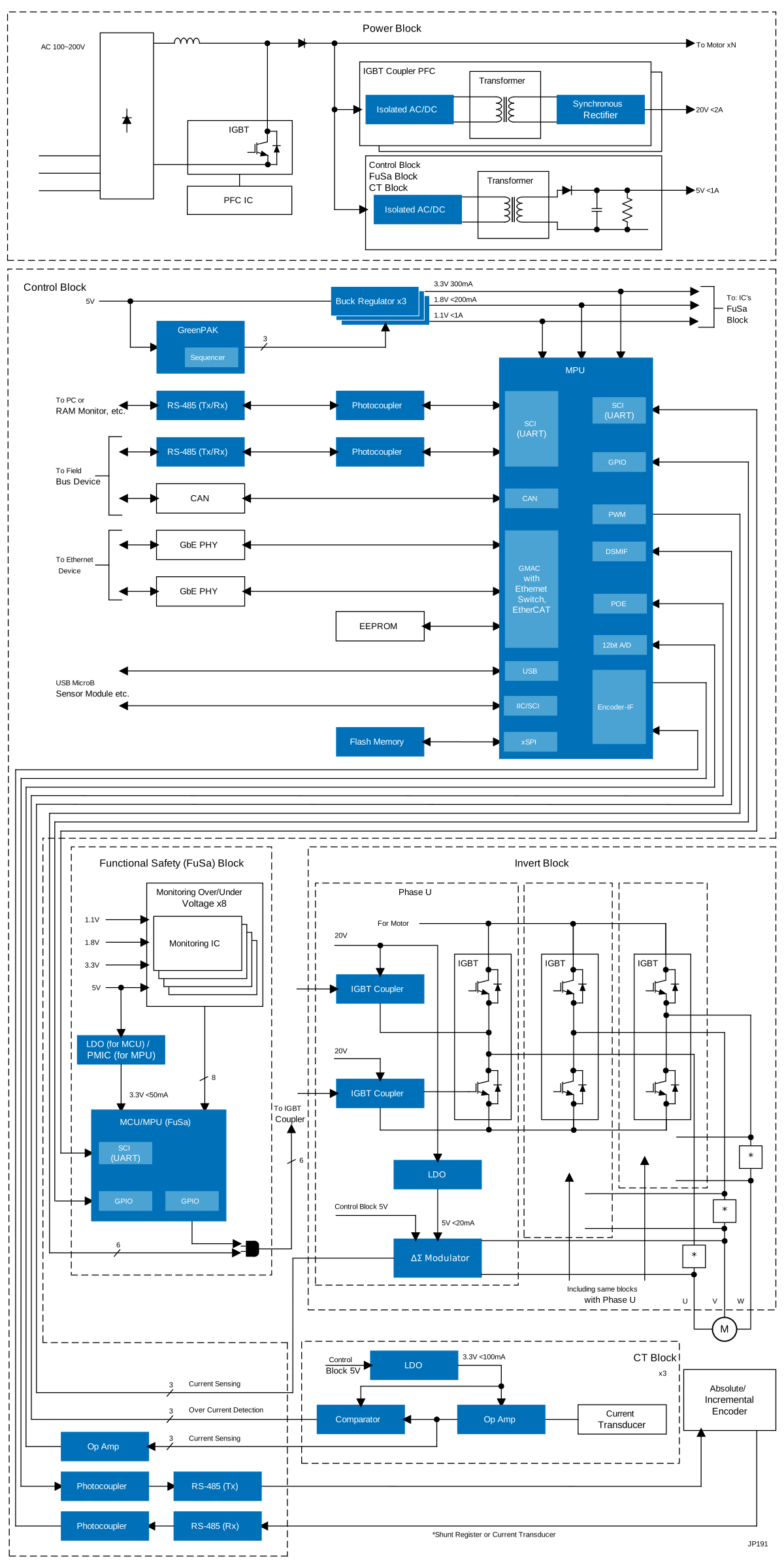 | 産業用ネットワーク&機能安全対応モータ制御システム このモータ制御システムは、MPUとMCUを統合して、効率的な産業用モータ制御とネットワーキングを実現します。 |
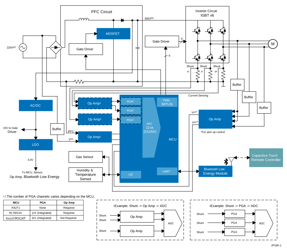 | スマートBLDCシーリングファン(PFC付き) スマートシーリングファンは、センサレスベクトル制御とリモートWi-Fi/Bluetooth LE操作により、空気質を向上させます。 |
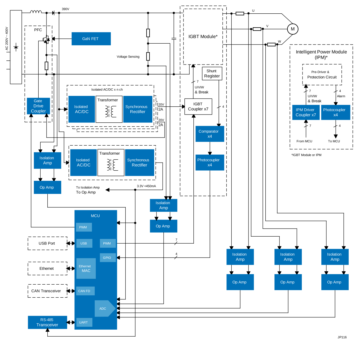 | ACドライブ&汎用インバータシステム このシステムは、ACドライブと汎用(GP)インバータの基本構成と必須コンポーネントを提供します。 |
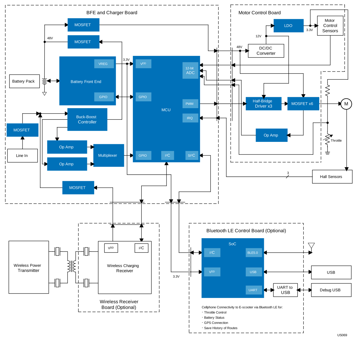 | 48Vモビリティプラットフォーム この48Vモビリティプラットフォームは、多様な電動モビリティアプリケーションに対応する汎用性と適応性に優れたソリューションを提供します。 |
 | 48V BLDC モータ位置制御 正確な制御、迅速なウェイクアップ、シームレスなコンポーネント統合を備えた効率的なBLDCモータシステム。 |