
Features
- AEC-Q100 compliant
- Supply voltage range: 3V to 32V
- Input offset voltage: ±1.2mV max.
- Input offset voltage temperature drift: ±1µV/°C typ.
- Gain-bandwidth product: 5MHz typ.
- Slew rate: 8.5V/µs typ.
- Stable with capacitive loads up to 1000pF
- Built-in phase correction circuit
- Built-in output short-circuit protection circuit
- Operating ambient temperature range: -40°C to +125°C
Description
The REAC844A is an automotive-grade, AEC-Q100-compliant quad bipolar operational amplifier that delivers a low input offset voltage (VIO ≤ ±1.2mV) over an ambient temperature range of -40°C to +125°C. It provides load capacitance stability and exhibits no crossover distortion. With its high slew rate, the REAC844A supports high-speed signal amplification and is suitable for multi-channel sensor and motor control applications.
Parameters
| Attributes | Value |
|---|---|
| Channels (#) | 4 |
| Temp. Range (°C) | -40 to +125 |
| Bandwidth (MHz) | 5 |
| Gain Min | 25000 |
| Offset Voltage (Max) (mV) | 1.2 |
| IBIAS (nA) | 6 |
| IOUT (A) | 0.02 |
| CMRR (dB) | 100 |
| Rail-to-Rail Input | No |
| Rail-to-Rail Output | No |
| Common Mode Input Voltage Range (V) | 3-32 |
| Output Voltage Swing Range (V) | VOL1+13.7(Min.)-13.7(Max), VOL2+13.5(Min.)-13.5(Max) |
| IS per Amp (mA) | 1.5 |
| Single Supply Voltage Range (V) | 3 - 32 |
| Slew Rate (V/µs) | 8.5 |
| VS (Min) (V) | 3 |
| VS (Max) (V) | 32 |
| Dual Supply Range (V) | V+-1.5(Min.), V+-16(Max.) |
| Input Offset Voltage Vio (Max) (mV (±)) | 1.2 |
| Supply Current Icc/Idd (Max) (mA) | 5.5 |
| Qualification Level | Automotive(AEC-Q100 Compliant) |
| Simulation Model Available | SPICE |
Package Options
| Pkg. Type | Pkg. Dimensions (mm) | Lead Count (#) | Pitch (mm) |
|---|---|---|---|
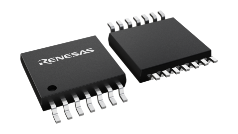
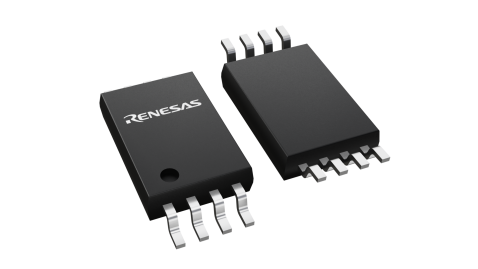
| TSSOP | 5 x 4.4 x 1.2 | 14 | 0.65 |
Product Comparison

Application Block Diagrams
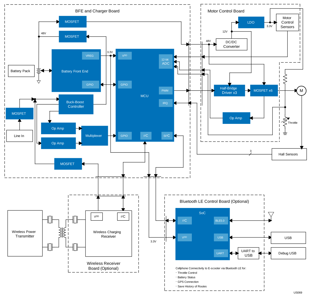 | 48V Mobility Platform This 48V mobility platform offers versatile, adaptable solutions for diverse electric mobility applications. |
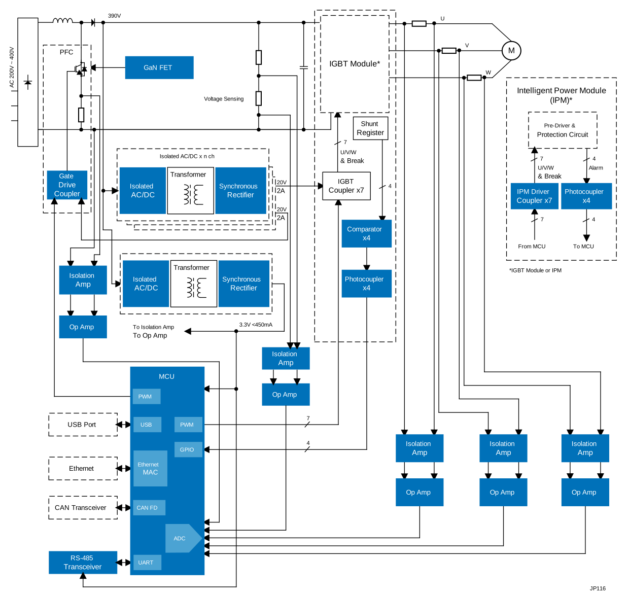 | AC Drive & General Purpose Inverter System This system provides a basic configuration and essential components for AC drives and general purpose (GP) inverters. |
 | 1.2kW High-Voltage GaN Inverter Efficient high-voltage GaN inverter with GaN-based PFC for industrial motor drives. |
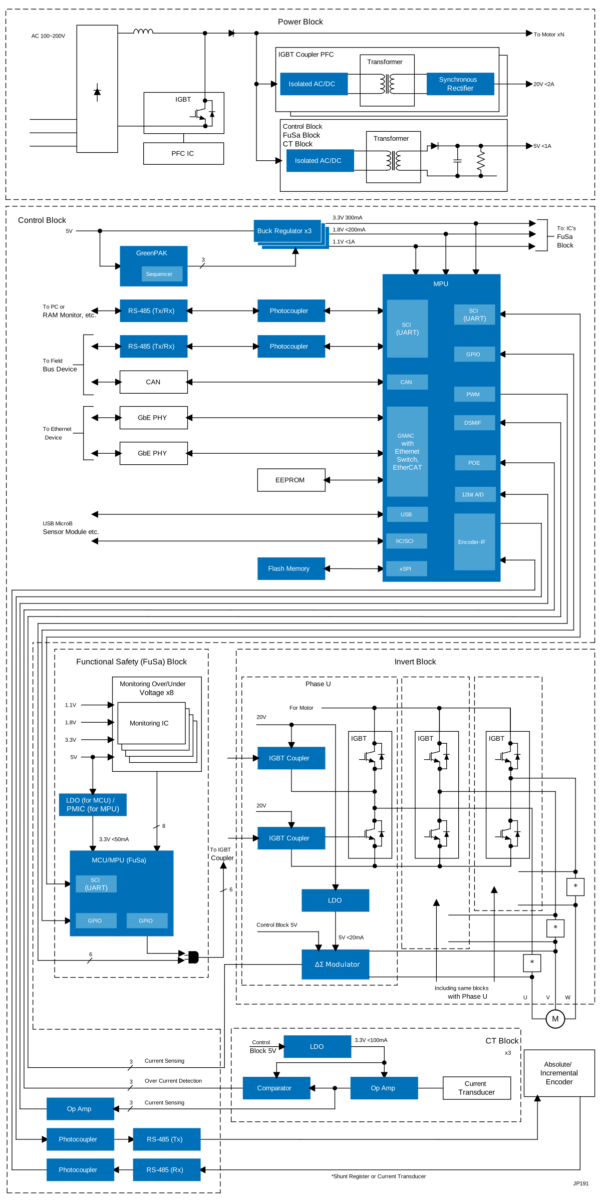 | Motor Control System with Industrial Network and Functional Safety This motor control system integrates MPU and MCU for efficient industrial motor control and networking. |
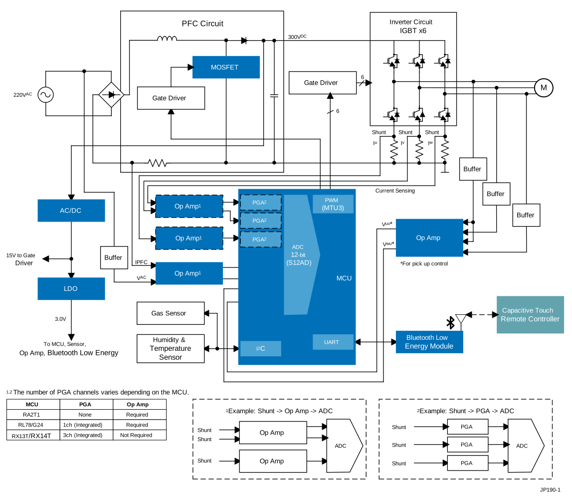 | Smart BLDC Ceiling Fan with PFC Smart ceiling fan enhances air quality with sensorless vector control and remote Wi-Fi/Bluetooth LE operation. |
 | 48V BLDC Motor Position Control Efficient BLDC motor system with precise control, rapid wake-up, and seamless component integration. |