
Features
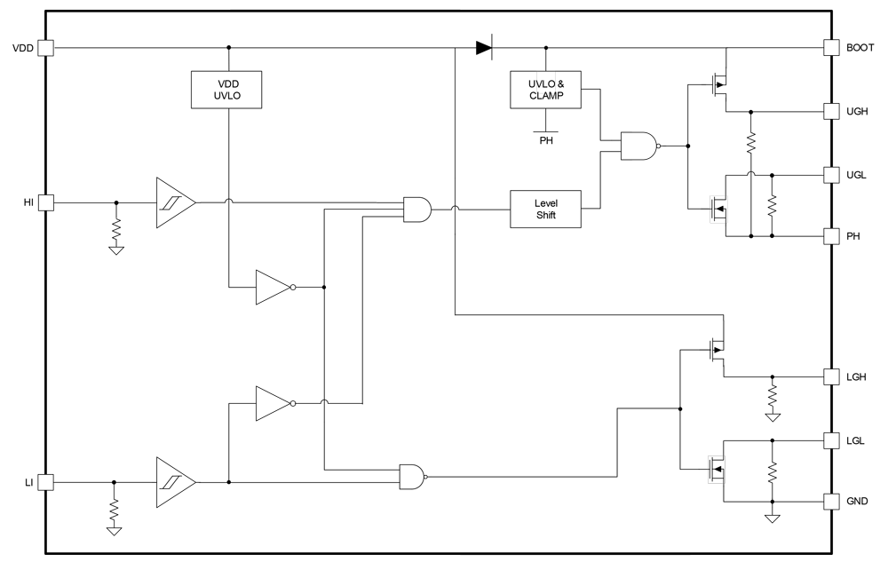
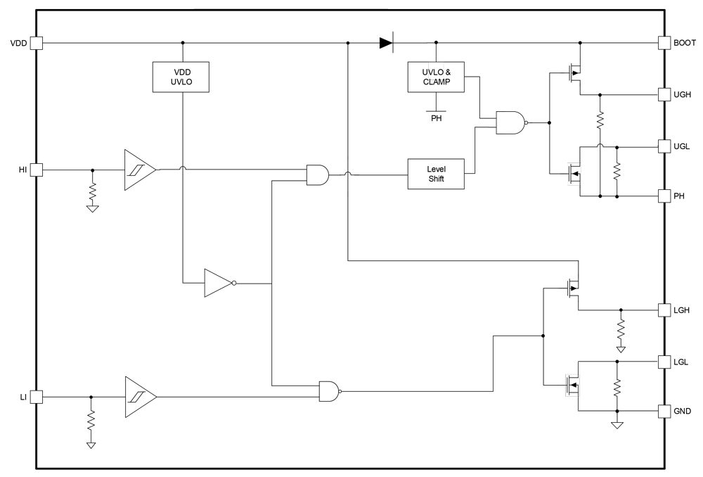
- Anti‑shoot‑through protection
- Independent high‑side and low‑side TTL logic inputs up to 14V, regardless of VDD voltage
- 3.3/5V CMOS logic‑level compatible input stage
- 100V PH voltage rating for high‑voltage applications
- 2A sourcing and 5.3A sinking peak drive current for GaN/MOSFETs
- Separately adjustable turn‑on and turn‑off speed
- Fast propagation delay (19ns/17ns typical)
- Excellent propagation delay matching (1.5ns typical)
- 4.5V to 5.5V bias supply with UVLO mechanism
- Integrated input and output pull‑down resistors
- 4.5ns typical rise time, 2.7ns typical fall time with 1nF load
- Small package: WLCSP12-2×2, FCQFN14-3×3
Description
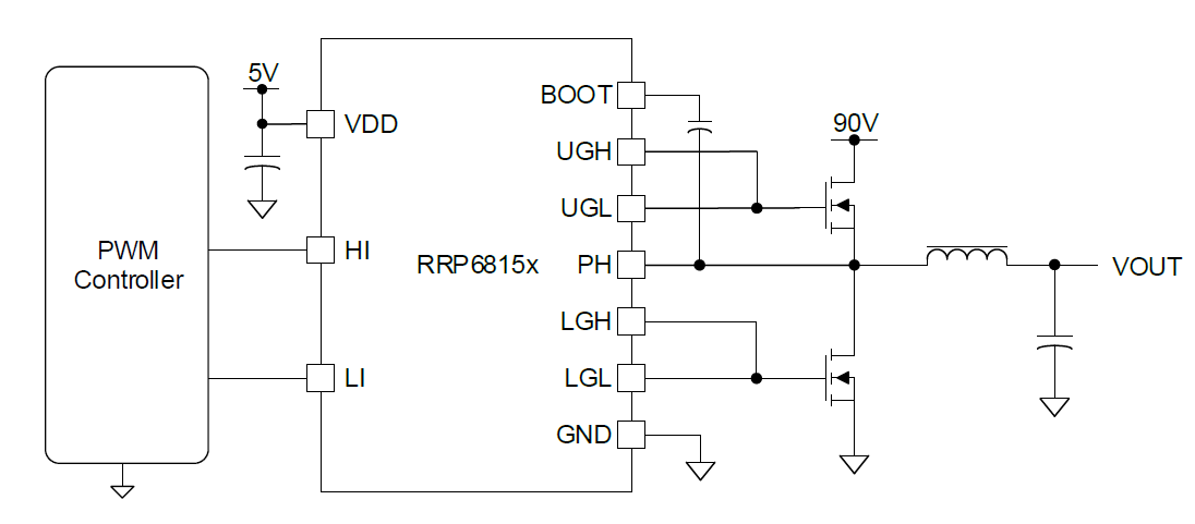
The RRP68150 is a 5V‑powered, high‑frequency half‑bridge driver optimized for enhancement‑mode GaN FETs and low‑threshold N‑channel MOSFETs. It delivers 2A source and 5.3A sink current capability, supporting a switching node up to 100V DC. The driver’s PWM inputs are compatible with 3.3V/5V CMOS logic and can tolerate up to 14V, independent of the VDD supply. The high‑side bias voltage uses a bootstrap technique and is internally clamped at 5.4V to prevent exceeding the GaN FET’s maximum gate‑source rating. A 5V operational supply simplifies power sharing with the controller.
As part of the RRP6815x driver family, the RRP68150 maintains consistent design and performance across related products. It integrates anti‑shoot‑through protection, which safeguards operation by preventing simultaneous conduction of the high‑side and low‑side FETs.
Parameters
| Attributes | Value |
|---|---|
| Bootstrap Supply Voltage (Max) (V) | 104 |
| VBIAS (Max) (V) | 5.5 |
| Peak Pull-up Current (A) | 2 |
| Peak Pull-down Current (A) | 5.3 |
| Turn-On Prop Delay (ns) | 19 |
| Turn-Off Prop Delay (ns) | 17 |
| Rise Time (μs) | 4.5 |
| Fall Time | 2.7ns |
| Temp. Range (°C) | -40 to +125°C |
| Input Logic Level | 3.3/5V CMOS |
| Qualification Level | standard |
| Simulation Model Available | iSim |
Package Options
| Pkg. Type | Pkg. Dimensions (mm) | Lead Count (#) | Pitch (mm) |
|---|---|---|---|
| QFN | 3.0 x 3.0 x 0.75 | 14 | 0.5 |
| WLCSP-TKCURDL | 1.9 x 1.9 x 0.50 | 6 | 0.4 |
Application Block Diagrams
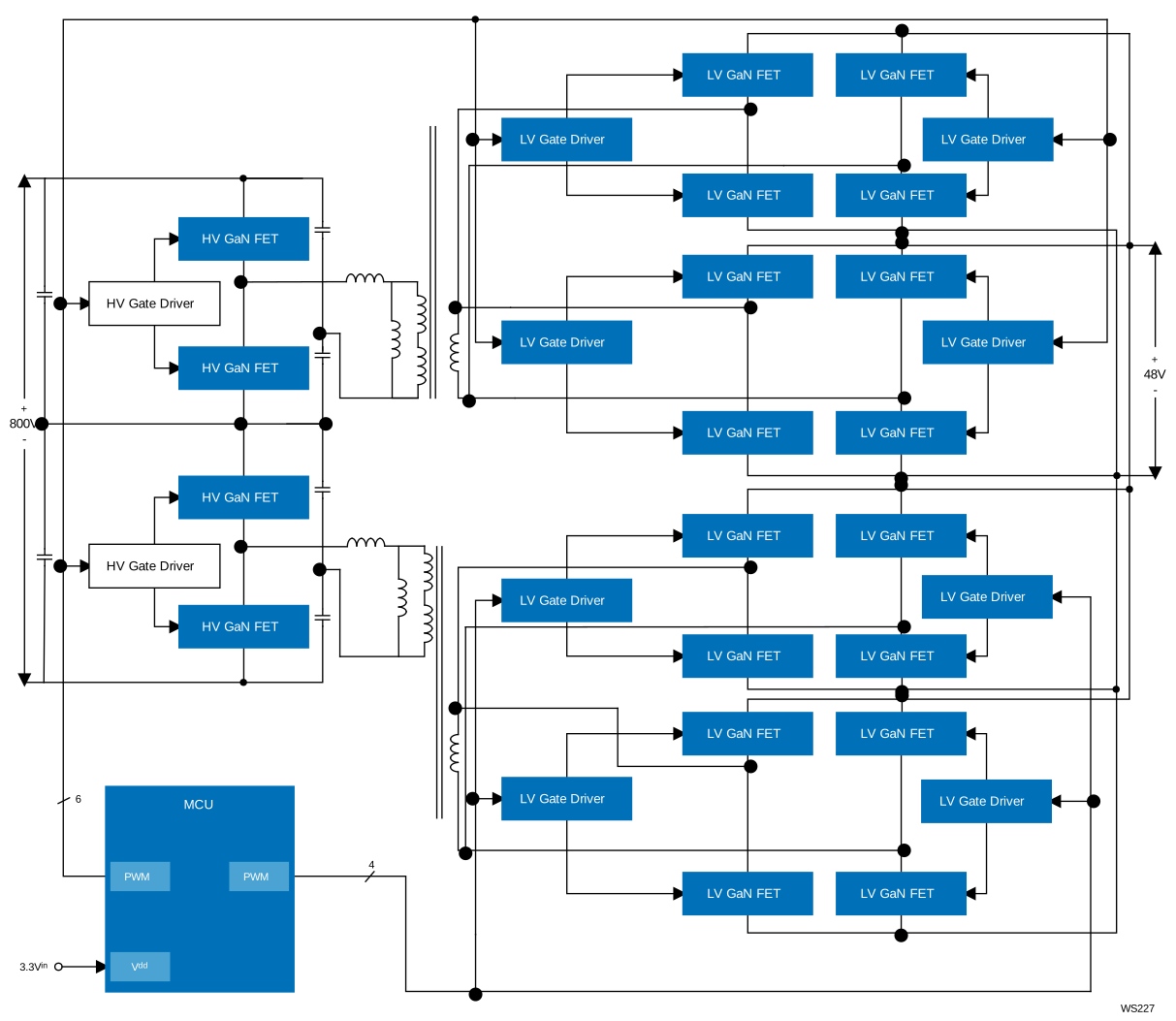 | 800V to 48V DCX System Efficiently converts an 800V DC bus to 48V DC with galvanic isolation for high-density, high-efficiency power delivery. |
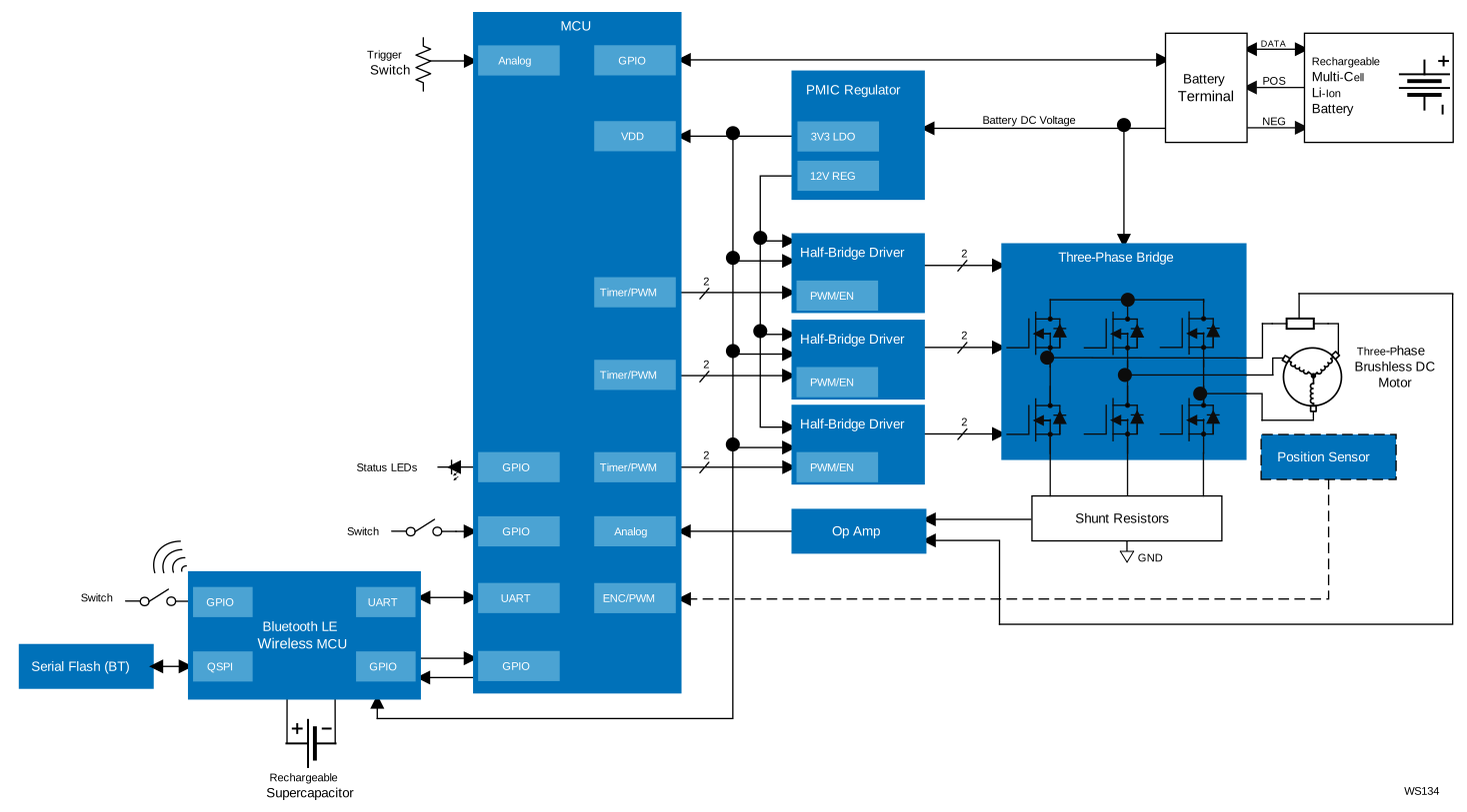 | Smart Cordless Brushless String Trimmer Next-gen cordless brushless string trimmer with GaN motor control, AI/ML adaptive cutting, and Bluetooth LE connectivity for smart, efficient operation. |
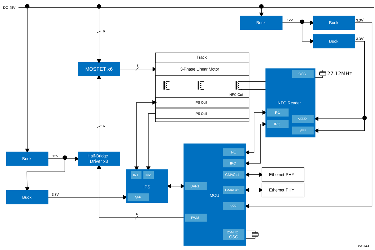 | Maglev Conveyor System Contactless maglev conveyor enables precise tracking, synchronized motion, and efficient power delivery for smart factories. |
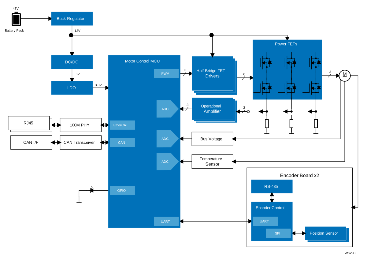 | DC Servo High-precision DC servo with responsive feedback and EtherCAT‑ready industrial motor control. |
Additional Applications
- Telecom/server Half-bridge and Full-bridge DC/DC Converters
- Half-bridge and Full-bridge Converters
- Synchronous Buck Converters
- Power Modules