
Overview
Description
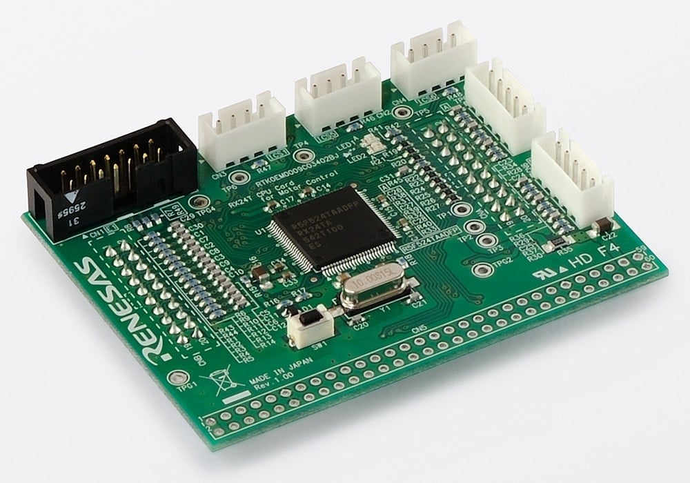
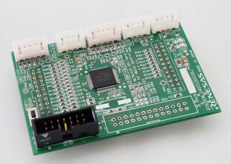
The CPU Card for Motor Control is an optional board for the Evaluation System for BLDC Motor. Using a CPU card and the evaluation system, users can easily evaluate motor control using the corresponding microcontroller offered by Renesas.
The CPU cards on this page have not been confirmed to be RoHS2 compliant.
Applications
Documentation
|
|
|
|
|---|---|---|
| Type | Title | Date |
| PCB Design Files | ZIP 742 KB | |
| Application Note |
PDF
3.17 MB
日本語
AI-generated Summary:
The software sample program enables sensorless vector control of permanent magnet synchronous motors using Renesas RX family microcontrollers. It supports both 2-shunt and 1-shunt current detection methods and integrates with Renesas Motor Workbench for motor control development and monitoring. The software targets multiple RX MCUs and provides reference implementations for motor control, including interrupt-driven control and MCU function allocation. The evaluation system includes hardware and software environments for testing and development, supporting various RX MCU models and inverter boards. The document details software configuration, control algorithms, and test results to facilitate motor control application development.
|
|
| PCB Design Files | 2nd motor extender board Design Package
|
|
| Application Note |
PDF
1.51 MB
日本語
AI-generated Summary:
Sensorless vector control software drives permanent magnetic synchronous motors using the RA6T1 microcontroller. It supports motor start/stop, A/D conversion, modulation, state transitions, startup methods, and system protection. The hardware includes a 24V DC power supply, inverter circuit, phase current detection, and user interfaces such as variable resistors, switches, and LEDs. The software integrates with Renesas Motor Workbench for development and debugging. The system uses a 48V inverter board and RA6T1 CPU card, with detailed hardware and software configurations provided. The package includes source code, control flowcharts, and evaluation environment setup.
|
|
| Manual - Development Tools | PDF 708 KB 日本語 | |
| Manual - Development Tools | PDF 652 KB 日本語 | |
| Manual - Development Tools | PDF 721 KB 日本語 | |
| Manual - Development Tools | PDF 872 KB 日本語 | |
| Manual - Development Tools | PDF 958 KB 日本語 | |
| Manual - Development Tools | PDF 842 KB 日本語 | |
| Application Note | Vector Control for Permanent Magnet Synchronous Motor with Encoder (For Evaluation System for BLDC Motor, Structure update version) Rev.1.00
AI-generated Summary:
Vector control software drives permanent magnet synchronous motors with encoders using Renesas microcontrollers. It integrates with the Motor Solution Kit and supports Renesas Motor Workbench for monitoring and UI control. The software utilizes multifunction timer pulse units and 12-bit A/D converters for precise motor control. Compatible MCUs include RX72M, RX72T, RX66T, RX24T, RX24U, RX23T, and RX13T. The development environment includes CS+ and e2studio IDEs with RX smart configurator and CC-RX toolchain. Hardware setup involves inverter boards and AMT102-V encoders. The package provides sample programs for vector control, motor control modules, and detailed software architecture for efficient motor operation.
|
|
| Application Note |
PDF
2.16 MB
日本語
AI-generated Summary:
This document explains implementing sensorless speed control of a permanent magnetic synchronous motor using 120-degree conducting control with initial position detection, based on the RL78/G1F microcontroller. It details the required hardware and software development environment, including specific microcontroller models, evaluation boards, and software versions. It also describes necessary hardware modifications to the 24V inverter board and RL78/G1F CPU card for current and voltage sensing, such as resistor changes and circuit adjustments to switch from 3-phase to DC-link current detection.
|
|
| Application Note |
PDF
1.60 MB
日本語
AI-generated Summary:
The document explains the implementation of sensorless 120-degree conducting control for permanent magnetic synchronous motors using the RX13T microcontroller. It details hardware and software configurations, including motor start/stop, speed and voltage control, and system protection functions. The control method uses sensorless algorithms for efficient motor operation. It also covers the use of Renesas Motor Workbench for motor control development and debugging. Hardware interfaces include analog inputs for speed commands and phase current/voltage measurements, PWM outputs for inverter control, and user interfaces such as switches and LEDs. The document provides sample programs compatible with CS+ and e2 studio IDEs and references related manuals for further technical details.
|
|
| Application Note |
PDF
2.01 MB
日本語
AI-generated Summary:
The document explains how to implement sensorless 120-degree conduction control for high-speed rotation of a permanent magnet synchronous motor (PMSM) using the RL78/G1F microcontroller. It details the hardware and software environment, including sample programs compatible with CS+ and e2studio IDEs, and demonstrates the use of Renesas Motor Workbench for motor control development. The hardware setup includes a demo board with specifications such as 12V-50V input voltage, 30A peak current, and various connectors for communication and sensor inputs. The document also provides a detailed hardware configuration diagram illustrating the connections between the microcontroller, inverter circuit, sensors, and communication interfaces.
|
|
| Application Note |
PDF
1.64 MB
日本語
AI-generated Summary:
The sensorless vector control method drives a permanent magnet synchronous motor (PMSM) using the RL78/G1F microcontroller. It includes sample programs compatible with CS+ and e2studio IDEs, designed for a 24V motor control evaluation system. The system uses hardware such as the RL78/G1F CPU card, inverter board, and TSUKASA TG-55L motor. The hardware configuration involves analog inputs for bus voltage and speed commands, PWM outputs for motor phases, and interfaces for start/stop, error reset, and LED indicators. The Renesas Motor Workbench tool supports motor control development. The document details hardware ports, user interfaces, and development environments to implement sensorless vector control algorithms effectively.
|
|
| Application Note |
PDF
1.03 MB
日本語
AI-generated Summary:
The document explains sensorless vector control implementation for permanent magnet synchronous motors using the RX23T microcontroller. It details the hardware and software development environments, including specific microcontroller models, evaluation boards, and toolchain versions. The hardware configuration covers input/output ports, sensors, and motor control signals. User interfaces such as variable resistors, switches, and LEDs are described, along with their functions for motor speed control, start/stop commands, error reset, and system reset.
|
|
| Application Note |
RX23T Vector control for permanent magnetic synchronous motor with encoder (Implementation) Rev.1.10
PDF
1.12 MB
日本語
AI-generated Summary:
The document explains sample programs for vector control of a permanent magnet synchronous motor with an encoder using RX23T. It details the hardware and software development environments, including specific microcontroller and evaluation boards. The system overview covers hardware configuration, showing connections for power, PWM outputs, encoder inputs, and sensors. User interfaces include variable resistors for speed input, toggle switches for motor control, LEDs for status indication, and port functions for various signals and controls.
|
|
| Application Note |
PDF
1.04 MB
日本語
AI-generated Summary:
The document explains how to implement sensorless vector control for permanent magnet synchronous motors using RX24T/RX24U microcontrollers. It details the hardware and software development environments, including specific microcontroller models, evaluation boards, and toolchain versions. The system overview covers hardware configuration, including input/output ports, inverter circuits, and user interfaces such as switches, LEDs, and variable resistors for speed control. It also specifies port functions for voltage, current measurement, PWM outputs, and error detection.
|
|
| Application Note |
PDF
1.08 MB
日本語
AI-generated Summary:
The document explains sample programs for vector control of permanent magnet synchronous motors with encoders using RX24T/RX24U microcontrollers. It details the hardware and software development environments, including specific microcontrollers, evaluation boards, and software toolchains. The hardware configuration includes various input/output ports for motor control, such as PWM outputs, encoder inputs, and user interfaces like switches and LEDs. It also describes the system's user interface components and their functions, such as rotation speed input, start/stop commands, error reset, and LED indicators.
|
|
| Application Note |
PDF
1.47 MB
日本語
AI-generated Summary:
The document explains how to implement 120-degree conducting control of a permanent magnetic synchronous motor (PMSM) using the RL78/G1F microcontroller. It details sample programs for motor control, supporting both Hall sensor and sensorless modes, configurable via software. The hardware setup includes a 24V inverter board, RL78/G1F CPU card, and motor, with user interfaces such as variable resistance for speed command, toggle switches for start/stop and error reset, and LEDs for status indication. The document also covers the use of Renesas Motor Workbench for motor control development and provides hardware and software environment specifications. Reference manuals and related application notes support deeper understanding and implementation.
|
|
| Application Note |
PDF
910 KB
日本語
AI-generated Summary:
Sensorless vector control software for permanent magnet synchronous motors (PMSM) uses the RX13T microcontroller and Renesas Motor Workbench libraries to enable motor control without position sensors. The system utilizes a 24V inverter board and RX13T CPU card, interfacing with hardware components such as variable resistors for speed input, toggle switches for motor start/stop and error reset, and LEDs for status indication. The control algorithm relies on sensorless vector control techniques, with PWM outputs managing the motor phases. Hardware includes A/D converters for bus voltage and phase current measurements, and overcurrent detection for safety. This setup supports efficient motor control development and evaluation.
|
|
| Manual - Development Tools | PDF 96 KB | |
| Other | PDF 209 KB | |
| Quick Start Guide | PDF 839 KB | |
| Application Note |
PDF
811 KB
日本語
AI-generated Summary:
The document explains how to implement sensorless vector control for permanent magnet synchronous motors using the RX72T microcontroller. It details the hardware and software development environments, including specific microcontroller models, evaluation boards, and toolchain versions. The system overview covers hardware configuration with input/output ports, sensors, and inverter circuits. User interfaces include variable resistors for speed control, toggle switches for motor start/stop and error reset, and LEDs indicating motor status and errors.
|
|
| Application Note |
RX72T Vector control for permanent magnetic synchronous motor with encoder (Implementation) Rev.1.00
PDF
962 KB
日本語
AI-generated Summary:
The document explains sample programs for vector control of a permanent magnet synchronous motor with an encoder using the RX72T microcontroller. It details the hardware and software development environment, including the RX72T MCU, 24V inverter board, and CC-RX toolchain. The system hardware configuration covers input/output ports, PWM outputs, encoder signals, and user interfaces such as switches and LEDs for motor control and status indication.
|
|
| Manual - Development Tools | PDF 1.71 MB 日本語 | |
| Application Note |
PDF
901 KB
日本語
AI-generated Summary:
The document explains the implementation of 120-degree conducting control for a permanent magnetic synchronous motor (PMSM) using hall sensors with the RX23T microcontroller. It details the hardware and software development environments, including the microcontroller, evaluation board, motor, and toolchain versions. The system overview covers hardware configuration, user interface components such as variable resistance for speed command, toggle switches for start/stop and error reset, and LED indicators. Port interfaces of the RX23T microcontroller are also specified, detailing connections for voltage measurement, current measurement, PWM outputs, hall sensor inputs, and emergency stop input.
|
|
| Application Note |
PDF
896 KB
日本語
AI-generated Summary:
The document explains the implementation of 120-degree conducting control for permanent magnetic synchronous motors using the RX23T microcontroller and Renesas Motor Workbench. It details the hardware and software development environment, including the RX23T microcontroller, 24V inverter board, and TG-55L motor. The system hardware configuration features analog inputs for bus voltage, phase currents, and voltages, along with user interfaces such as variable resistance for speed command, toggle switches for start/stop and error reset, and LED indicators. Port interfaces of the RX23T microcontroller are listed with their functions, including PWM outputs and emergency stop input.
|
|
| Application Note |
PDF
910 KB
日本語
AI-generated Summary:
The document explains the implementation of 120-degree conducting control for permanent magnetic synchronous motors (PMSM) using hall sensors with the RX24T microcontroller. It details the hardware and software development environment, including the RX24T microcontroller, inverter board, motor, and Renesas CCRX toolchain. The system hardware configuration covers sensor inputs, motor phases, PWM outputs, and user interfaces such as switches and LEDs for motor control and error handling.
|
|
| Application Note |
PDF
895 KB
日本語
AI-generated Summary:
This document explains the implementation of 120-degree conducting control for a permanent magnetic synchronous motor (PMSM) using the RX24T microcontroller. It details the hardware and software development environments, including the RX24T microcontroller, 24V inverter board, and motor TG-55L. The system overview covers hardware configuration with input/output ports, sensors, and control signals. User interface components such as variable resistance for speed command, toggle switches for start/stop and error reset, and LED indicators are described along with their functions and port assignments.
|
|
| Manual - Development Tools | PDF 252 KB | |
| Other | PDF 226 KB | |
| Manual - Development Tools | PDF 562 KB | |
| Application Note |
PDF
557 KB
日本語
AI-generated Summary:
The document explains sensorless vector control for Permanent Magnet Synchronous Motors (PMSM) using a two-phase (d, q) coordinate system instead of the three-phase system. It details the coordinate transformation, voltage equations, and torque generation, distinguishing between magnet torque and reluctance torque. The control system design includes speed and current control blocks using PI controllers and decoupling control to independently manage d-axis and q-axis currents, enhancing response and control precision.
|
|
| Application Note |
PDF
529 KB
日本語
AI-generated Summary:
Vector control of Permanent Magnet Synchronous Motors (PMSM) uses a two-phase (d, q) coordinate system aligned with the motor's magnetic flux. The d-axis corresponds to the magnetic flux direction, and the q-axis is orthogonal. This method transforms three-phase currents into two-phase currents, simplifying control. Torque consists of magnet torque and reluctance torque, with non-salient PMSMs having zero reluctance torque. The control system integrates position, speed, and current control using PI and P controllers, with decoupling control enabling independent d-axis and q-axis voltage commands for high-speed response.
|
|
| Application Note |
PDF
815 KB
日本語
AI-generated Summary:
The document explains the implementation of sensorless vector control for permanent magnet synchronous motors using the RX66T microcontroller. It details the hardware and software development environments, including the use of Renesas Motor Workbench and specific tools and versions. The hardware configuration includes the RX66T MCU, a 24V inverter board, and the TG-55L motor. User interfaces such as variable resistors, toggle switches, LEDs, and push switches control motor speed, start/stop, error reset, and system reset. Port assignments for voltage, current measurements, PWM outputs, and emergency stop inputs are also specified.
|
|
| Application Note |
RX66T Vector control for permanent magnetic synchronous motor with encoder (Implementation) Rev.1.00
PDF
959 KB
日本語
AI-generated Summary:
The document explains sample programs for vector control of a permanent magnet synchronous motor with encoder using RX66T microcontroller. It details the hardware and software development environments, including specific microcontroller boards and toolchains. The hardware configuration includes inputs from analog sensors, switches, LEDs, and encoder signals, with PWM outputs controlling the motor phases. User interfaces such as speed input, start/stop switches, error reset, and status LEDs are described with corresponding port assignments.
|
|
| Manual - Development Tools | PDF 184 KB | |
| Other | PDF 291 KB | |
| Manual - Development Tools | PDF 1.90 MB | |
| Application Note |
PDF
1.91 MB
日本語
AI-generated Summary:
The document details the implementation of sensorless speed control for a permanent magnetic synchronous motor (PMSM) using 120-degree conducting control with the RL78/G14 microcontroller. It describes the hardware setup, including the RL78/G14 MCU, 24V inverter board, and TG-55L-KA motor. The system uses analog inputs for speed commands and phase voltage measurements, toggle switches for motor control and error reset, and LEDs for status indication. Port assignments and hardware specifications are provided for precise control and monitoring.
|
|
| Application Note |
PDF
3.00 MB
日本語
AI-generated Summary:
The document explains how to implement sensorless detection of the rotor's initial position in a permanent magnetic synchronous motor using the RL78/G1F microcontroller and Renesas Motor Workbench. It details the development environment, including hardware such as the RL78/G1F microcontroller, 24V inverter board, and TG-55L motor, and software tools like CS+ and e2studio with specific toolchain versions. It also describes necessary hardware modifications to the evaluation board, including changing from a 3-shunt to a 1-shunt current detection method and adjusting resistors and capacitors for accurate phase voltage sensing.
|
|
| Application Note |
PDF
1.73 MB
日本語
AI-generated Summary:
The document explains the implementation of 120-degree conducting control for permanent magnetic synchronous motors (PMSM) using Hall sensors with the RL78/G14 microcontroller. It details the hardware and software development environments, including specific microcontroller models, evaluation boards, and software versions. The system overview covers hardware configuration, showing connections between the microcontroller, inverter, motor, sensors, and user interfaces such as switches, LEDs, and variable resistors. Port assignments for sensor inputs, PWM outputs, and control signals are also specified.
|
|
| Manual - Development Tools | PDF 699 KB | |
| Manual - Development Tools | PDF 1.58 MB | |
| Manual - Development Tools | PDF 862 KB 日本語 | |
| Other | PDF 65 KB | |
| Application Note |
PDF
1.95 MB
日本語
AI-generated Summary:
This document explains how to implement 120-degree conducting control of a permanent magnetic synchronous motor (PMSM) using Hall sensors with the RL78/G1G microcontroller. It details the hardware and software development environments, including specific microcontroller models, evaluation boards, and software tools. It also describes necessary modifications to the 24V inverter board and RL78/G1G CPU card, such as removing and connecting specific components, and changing the overcurrent detection method from INTP0 to PGA+CMP0, CMP1 by altering the shunt resistor configuration.
|
|
| Manual - Development Tools | PDF 636 KB | |
| Manual - Development Tools | PDF 328 KB | |
| Manual - Development Tools | PDF 1.30 MB 日本語 | |
| Manual - Development Tools | PDF 1.68 MB | |
| Manual - Development Tools | PDF 1.39 MB | |
| Other | PDF 317 KB | |
| Other | PDF 222 KB | |
| Application Note |
PDF
1.99 MB
日本語
AI-generated Summary:
The document explains how to implement 120-degree conducting control for permanent magnetic synchronous motors using the RL78/G1G microcontroller. It details the development environment including hardware like the RL78/G1G CPU Card and 24V inverter board, and software tools such as CS+ and estudio with their respective toolchain versions. It also describes necessary hardware modifications to the evaluation boards, including changes to the VR1 input port and adjustments for overcurrent detection methods, such as switching from 3-Shunt to 1-Shunt configuration on the inverter board.
|
|
| Manual - Development Tools | PDF 340 KB | |
| Manual - Development Tools | PDF 1.16 MB | |
| Manual - Development Tools | PDF 708 KB | |
| Manual - Development Tools | PDF 384 KB | |
| Other | PDF 255 KB | |
| Other | PDF 279 KB | |
|
63 items
|
||
Design & Development
Software & Tools
Software & Tools
| Software title
|
Software type
|
Company
|
|---|---|---|
| Renesas Motor Workbench Renesas Motor Workbench is a development support tool for debugging, analyzing, and tuning motor control programs.
|
Solution Toolkit | Renesas |
1 item
|
||
Sample Code
Sample Code
Filters
|
||
|---|---|---|
| Type | Title | Date Date |
| Sample Code | Sensorless Vector Control for Permanent Magnet Synchronous Motor (For Evaluation System for BLDC Motor, structure update version) Rev.1.20
[Toolchains=CC-RX|V3.06]
ZIP
150.22 MB
日本語
Application:
Industrial
Compiler:
CC-RX
Function:
Application Example
IDE:
CS+ for CC, e2 studio
|
|
| Sample Code | RA6T1 Sensorless vector control for permanent magnet synchronous motor (Implementation)
|
|
| Sample Code | Vector Control for Permanent Magnet Synchronous Motor with Encoder (For Evaluation System for BLDC Motor, Structure update version) Rev.1.00 - Sample Code
|
|
| Sample Code | RL78G1F Sensorless speed control of 120-degree conducting controlled permanent magnetic synchronous motor with detection of initial position (Implementation) Rev.2.00 - Sample Code
Application:
Motor Drives
Compiler:
CC-RL
Function:
Three-Phase Inverter Control
IDE:
CS+, e2 studio
|
|
| Sample Code | RX13T Vector Control for Permanent Magnet Synchronous Motor with Encoder (Implementation) For “Evaluation System for BLDC Motor" Rev.1.00 - Sample Code
Application:
Industrial
Compiler:
CC-RX
Function:
Application Example
IDE:
CS+, e2 studio
|
|
| Sample Code | RX13T Sensorless Vector Control for Permanent Magnet Synchronous Motor (Implementation) For “Evaluation System for BLDC Motor" Rev.1.10 - Sample Code
Application:
Industrial
Compiler:
CC-RX
Function:
Application Example
IDE:
CS+, e2 studio
|
|
| Sample Code | RX23T Sensorless Vector Control for Permanent Magnet Synchronous Motor (Implementation) For “Evaluation System for BLDC Motor" Rev.1.10 - Sample Code
Application:
Industrial
Compiler:
CC-RX
Function:
Application Example
IDE:
CS+, e2 studio
|
|
| Sample Code | RX23T Vector Control for Permanent Magnet Synchronous Motor with Encoder (Implementation) For “Evaluation System for BLDC Motor" Rev.1.10 - Sample Code
Application:
Industrial
Compiler:
CC-RX
Function:
Application Example
IDE:
CS+, e2 studio
|
|
| Sample Code | RX24T/RX24U Sensorless Vector Control for Permanent Magnet Synchronous Motor (Implementation) For “Evaluation System for BLDC Motor" Rev.1.10 - Sample Code
Application:
Industrial
Compiler:
CC-RX
Function:
Application Example
IDE:
CS+, e2 studio
|
|
| Sample Code | RX24T/RX24U Vector Control for Permanent Magnet Synchronous Motor with Encoder (Implementation) For “Evaluation System for BLDC Motor" Rev.1.10 - Sample Code
Application:
Industrial
Compiler:
CC-RX
Function:
Application Example
IDE:
CS+, e2 studio
|
|
| Sample Code | RX66T Sensorless Vector Control for Permanent Magnet Synchronous Motor (Implementation) For “Evaluation System for BLDC Motor" Rev.1.10 - Sample Code
Application:
Industrial
Compiler:
CC-RX
Function:
Application Example
IDE:
CS+, e2 studio
|
|
| Sample Code | RX66T Vector Control for Permanent Magnet Synchronous Motor with Encoder (Implementation) For “Evaluation System for BLDC Motor" Rev.1.10 - Sample Code
Application:
Industrial
Compiler:
CC-RX
Function:
Application Example
IDE:
CS+, e2 studio
|
|
| Sample Code | RX72T Sensorless Vector Control for Permanent Magnet Synchronous Motor (Implementation) For “Evaluation System for BLDC Motor" Rev.1.10 - Sample Code
Application:
Industrial
Compiler:
CC-RX
Function:
Application Example
IDE:
CS+, e2 studio
|
|
| Sample Code | RX72T Vector Control for Permanent Magnet Synchronous Motor with Encoder (Implementation) For “Evaluation System for BLDC Motor" Rev.1.10 - Sample Code
Application:
Industrial
Compiler:
CC-RX
Function:
Application Example
IDE:
CS+, e2 studio
|
|
| Sample Code | RX13T Sensorless 120-degree conducting control for permanent magnetic synchronous motor (Implementation) with “Evaluation System for BLDC Motor" Rev.1.00 - Sample Code
|
|
| Sample Code | RL78/G1F Sensorless 120-degree conducting control for permanent magnetic synchronous motor (high-speed rotation) Rev.1.00 - Sample Code
Application:
Motor Drives
Compiler:
CC-RL
Function:
Three-Phase Inverter Control
IDE:
CS+ for CC, e2 studio
|
|
| Sample Code | RL78/G1F Sensorless vector control for permanent magnetic synchronous motor Rev.2.00 - Sample Code
Application:
Motor Drives
Compiler:
CC-RL
Function:
Three-Phase Inverter Control
IDE:
CS+ for CC, e2 studio
|
|
| Sample Code | RX23T Sensorless vector control for permanent magnetic synchronous motor (Implementation) Rev.1.10 - Sample Code
|
|
| Sample Code | RX23T Vector control for permanent magnetic synchronous motor with encoder (Implementation) Rev.1.10 - Sample Code
|
|
| Sample Code | RX24T/RX24U Sensorless vector control for permanent magnetic synchronous motor (Implementation) Rev.1.10 - Sample Code
|
|
| Sample Code | RX24T/RX24U Vector control for permanent magnetic synchronous motor with encoder (Implementation) Rev.1.10 - Sample Code
|
|
| Sample Code | RL78/G1F 120-degree conducting control of permanent magnetic synchronous motor (Implementation) Rev.2.00 - Sample Code
|
|
| Sample Code | RX72T Sensorless vector control for permanent magnetic synchronous motor (Implementation) Rev.1.00 - Sample Code
|
|
| Sample Code | RX72T Vector control for permanent magnetic synchronous motor with encoder (Implementation) Rev.1.00 - Sample Code
|
|
| Sample Code | RX23T 120-degree conducting control of permanent magnetic synchronous motor using hall sensors (Implementation) Rev.1.01 - Sample Code
|
|
| Sample Code | RX23T Sensorless 120-degree conducting control of permanent magnetic synchronous motor (Implementation) Rev.1.11 - Sample Code
|
|
| Sample Code | RX24T 120-degree conducting control of permanent magnetic synchronous motor using hall sensors (Implementation) Rev.1.01 - Sample Code
|
|
| Sample Code | RX24T Sensorless 120-degree conducting control of permanent magnetic synchronous motor (Implementation) Rev.1.01 - Sample Code
|
|
| Sample Code | RX66T Sensorless vector control for permanent magnetic synchronous motor (Implementation) Rev.1.00 - Sample Code
|
|
| Sample Code | RX66T Vector control for permanent magnetic synchronous motor with encoder (Implementation) Rev.1.00 - Sample Code
|
|
| Sample Code | Sensorless Speed control of 120-degree conducting controlled permanent magnetic synchronous motor (Implementation) Rev.1.00 - Sample Code
|
|
| Sample Code | Sensorless detection of initial position of the rotor Rev.1.10 - Sample Code
|
|
| Sample Code | Speed control of 120-degree conducting controlled permanent magnetic synchronous motor using hall sensors (Implementation) - Sample Code (r01an4028ej0100)
|
|
| Sample Code | Speed control of 120-degree conducting controlled permanent magnetic synchronous motor using hall sensors (Implementation) - Sample Code (r01an3736ej0100)
|
|
| Sample Code | RL78/G1G Sensorless Speed control of 120-degree conducting controlled permanent magnetic synchronous motor (Implementation) Rev.1.00 - Sample Code
|
|
|
35 items
|
||
Related Boards & Kits
Boards & Kits

Evaluation System for BLDC Motor
The Evaluation System for BLDC Motor provided by Renesas is a low-voltage permanent magnet synchronous motor (brushless DC motor) solution that allows anyone to easily evaluate the motor in combination with a CPU card for motor control. After purchase, you can download the software from the... Read More
Product Options
| Part Number | Status | Stock | Budgetary Price (USD) | Description |
|---|---|---|---|---|
| RTK0EM0003C01202BJ | Active | Out of Stock | RX23T CPU card, onboard device: R5F23T5ADFM | |
| RTK0EM0009C03402BJ | Active | Out of Stock | RX24T CPU card, onboard device: R5F24TAADFP | |
| RTK0EMA170C00000BJ | Active | In Stock | 1u | $71.28 | RA6T1 CPU Card, onboard device: R7FA6T1AD3CFP |
| RTK0EML240C03000BJ | Active | In Stock | 1u | $67.06 | RL78/G1F CPU card, onboard device: R5F11BLEAFB |
| RTK0EMX590C02000BJ | Active | In Stock | 1u | $98.94 | RX24U CPU card, onboard device: R5F524UEADFB |
| RTK0EMX870C00000BJ | Active | In Stock | 1u | $82.35 | RX66T CPU card, onboard device: R5F566TEADFP |
| RTK0EMX990C00000BJ | Active | In Stock | 1u | $95.29 | RX72T CPU card, onboard device: R5F572TKCDFB |
| RTK0EMXA10C00000BJ | Active | In Stock | 1u | $41.41 | RX13T CPU card, onboard device: R5F513T5ADFL |
| RTK0EMXDE0C00000BJ | Active | In Stock | 1u | $100 | RX72M CPU Card with RDC-IC, onboard device: R5F572MNDDBD |
Videos & Training
Additional Videos
News & Blog Posts
Blog Post Nov 15, 2021 |
Blog Post Jun 1, 2021 |
Support
Support Communities
- RX24T E2 Lite Debug
Hi. I am trying to debug my code in e2 studio for an RX24T device (FINE interface). When I try to connect, I am getting the following output: PowerSuppy() Failed RxTargetDevice::startConnection() Rx_Init_E1_E20() Failed I verified connection to the micro using the "renesas flash programmer 3.19 ...
Sep 16, 2025

Support Communities

Knowledge Base


