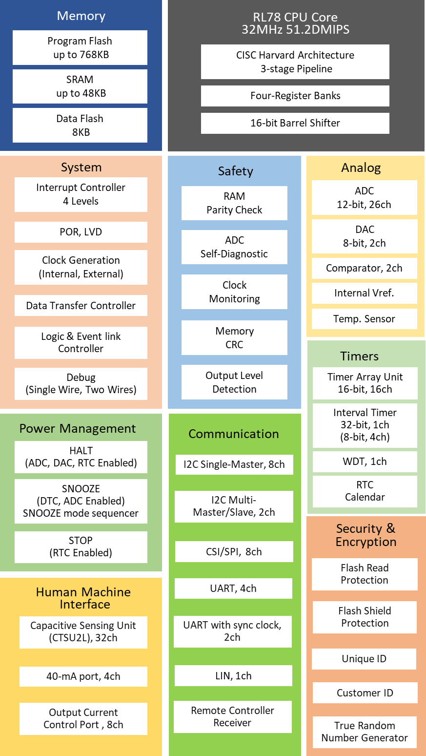
Features
- CPU: RL78 core, Max. 32MHz
- Up to 768kB Flash Memory and 48kB SRAM
- Memory: SRAM up to 48KB, Program Flash up to 768KB
- 8KB Data Flash to store data as in EEPROM
- Scalable from 30-pin to 128-pin packages
- Wide operating voltage range of 1.6V to 5.5V
- Enhanced Capacitive Sensing Unit (CTSU2L)
- Timer: 16-bit Timer (ch) x 16, 8-bit Timer, Watchdog Timer (ch) x 1,32-bit Interval Timer (ch) x 1
- PWM: PWM Output x 14
- Analog function: 12-bit A/D Converter (ch) x 26, 8-bit D/A - Converter (ch) x 2, Comparator x 2
- On-chip Oscillator Freq. (MHz): High-Speed: up to 32MHz
- Middle-Speed: up to 4MHz
- Low-speed: 32.768kHz
- Snooze mode sequencer
- Logic & Event link controller
- Others: RTC, Power-On Reset, Low Voltage Detection
- A large selection of packages (LQFP, QFN, LGA, BGA, WLCSP)


Description
The RL78/G23 microcontroller group is a new generation of the RL78 family of microcontrollers, with 41μA/MHz CPU operation. The RL78/G23 group has the industry’s lowest power consumption with 210nA at stop (4KB SRAM retention), and a snooze mode sequencer which significantly reduces power consumption during intermittent operation. The RL78/G23 group features a wide operating voltage range of 1.6V to 5.5V at up to 32MHz, a broad range of package pin counts from 30 pins to 128 pins, and up to 768KB of flash memory. In addition to enhanced analog and security features, it also incorporates logic and event link controllers (ELCL) and the first capacitive touch sensing unit (CTSU2L) in the RL78 family. A rich development environment is also provided for the RL78/G23, including a fast prototyping board. This board allows users to write and debug programs with an easy-to-use GUI, by simply connecting a USB cable and a smart configurator without any additional tools required. The RL78/G23 is compatible with the existing RL78 family and can be a seamless replacement, making it suitable for a wide range of applications, from home appliance and consumer electronics to industrial equipment.
Parameters
| Attributes | Value |
|---|---|
| Program Memory (KB) | 96, 128, 192, 256, 384, 512, 768 |
| Data Flash (KB) | 8 |
| RAM (KB) | 12, 16, 20, 24, 32, 48 |
| Carrier Type | Full Carton (Tray), Full Tray (Tray), Tape & Reel |
| Supply Voltage (V) | - |
| I/O Ports | 26, 28, 32, 36, 40, 44, 48, 58, 74, 92, 120 |
| Temp. Range (°C) | -40 to +85, -40 to +105 |
| Operating Freq (Max) (MHz) | 32 |
| USB FS (host ch/device ch) | ( 0 / 0 ) |
| SCI or UART (ch) | 3, 4, 5, 6 |
| SPI (ch) | 3, 4, 5, 6, 8 |
| I2C (#) | 4, 5, 6, 7, 8, 10 |
| CAN (ch) | 0 |
| CAN-FD (ch) | 0 |
| Wireless | No |
| LIN (#) | 1 |
| 16-Bit Timer (ch) (#) | 8, 12, 16 |
| 12-Bit A/D Converter (ch) | 8, 9, 10, 12, 17, 20, 26 |
| 10-Bit A/D Converter (ch) | 0 |
| 24-Bit Sigma-Delta A/D Converter (ch) | 0 |
| 12-Bit D/A Converter (ch) | 0 |
| 10-Bit D/A Converter (ch) (#) | 0 |
| 8-Bit D/A Converter (ch) | 2 |
| Capacitive Touch Sensing Unit (ch) | 2, 3, 5, 6, 7, 8, 10, 11, 12, 13, 14, 16, 20, 22, 30, 32 |
| Segment LCD Controller | No |
| Security & Encryption | Unique ID,TRNG |
Package Options
| Pkg. Type | Pkg. Dimensions (mm) | Lead Count (#) | Pitch (mm) |
|---|---|---|---|
| HWQFN | 5 x 5 x 0.8 | 32 | 0.5 |
| HWQFN | 6 x 6 x 0.8 | 40 | 0.5 |
| HWQFN | 7 x 7 x 0.8 | 48 | 0.5 |
| LFQFP | 7 x 7 x 1.7 | 48 | 0.5 |
| LFQFP | 10 x 10 x 1.7 | 64 | 0.5 |
| LFQFP | 12 x 12 x 1.7 | 80 | 0.5 |
| LFQFP | 14 x 14 x 1.7 | 100 | 0.5 |
| LFQFP | 20 x 14 x 1.6 | 128 | 0.5 |
| LQFP | 7 x 7 x 1.7 | 32 | 0.8 |
| LQFP | 10 x 10 x 1.6 | 44 | 0.8 |
| LQFP | 10 x 10 x 1.7 | 52 | 0.65 |
| LQFP | 12 x 12 x 1.6 | 64 | 0.65 |
| LQFP | 14 x 14 x 1.7 | 80 | 0.65 |
| LQFP | 20 x 14 x 1.6 | 100 | 0.65 |
| LSSOP | 9.85 x 6.1 x 1.4 | 30 | 0.65 |
| WFLGA | 4 x 4 x 0.76 | 36 | 0.5 |
| WFLGA | 5 x 5 x 0.76 | 64 | 0.5 |
Application Block Diagrams

|
Smart Home Central Control Box
Smart home control box integrates devices, monitors conditions, and manages lighting and appliances.
|

|
Intelligent Lighting System for Building Automation
Intelligent lighting system with DALI-2 and customizable dimming for building automation.
|

|
Heat Pump Control System
This heat pump system features motor control MCU, PLC, and Wi-Fi connectivity for optimized performance.
|

|
High-Efficiency Induction Heaters
High-efficiency induction technology for rapid, uniform heating with energy-saving features.
|

|
PC Water Cooling System with Wireless Control
Advanced PC water cooler with wireless control, efficient heat dissipation, and flexible configurations.
|

|
Versatile Drive Circuit for Heating & Inductive Applications
Versatile drive circuit for precise heating, motor control, and power management with robust protection.
|

|
Smart Waste Bin
Smart waste bins monitor the environment and trash levels and ensure efficient communication.
|

|
Critical Power Monitoring System
Critical power monitoring system utilizes NB‑IoT or Cat‑M1, MCU, sensors, and battery backup.
|

|
Smart Solar Battery Charger
Smart solar battery charger ensures efficient battery use, protects against overcharging, and adapts to variable inputs.
|
Additional Applications
- General Purpose
- Consumer applications
- Home Appliance
- Industrial Automation
- Building Automation
This video demonstrates how to import sketches using the RL78 Arduino library into e² studio, as well as how to build and debug them. By debugging in e² studio, you can obtain detailed information and verify the internal workings of the library, which is not possible with the Arduino IDE.
Related Resources
News & Blog Posts
Blog Post
Apr 1, 2025
|
Blog Post
Dec 18, 2023
|
Blog Post
Aug 10, 2023
|
Blog Post
Jun 29, 2023
|
Blog Post
May 30, 2023
|
Blog Post
Apr 25, 2023
|
Blog Post
Mar 17, 2023
|
Blog Post
Oct 25, 2022
|
Blog Post
Jun 30, 2022
|
Blog Post
Apr 13, 2021
|