
Overview
Description
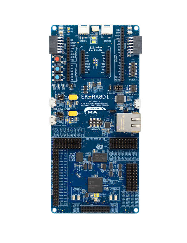
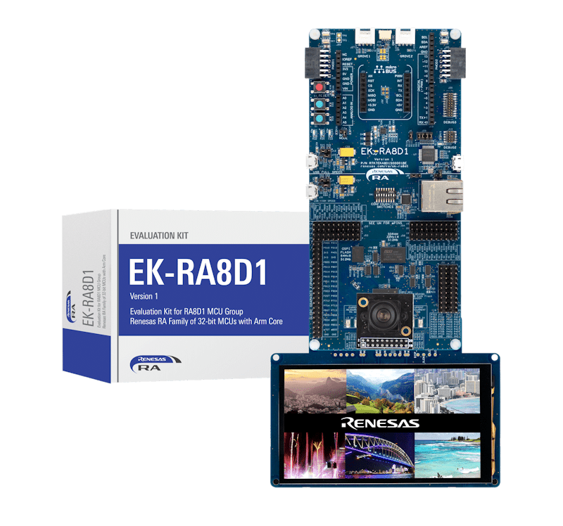
The EK-RA8D1 evaluation kit enables users to effortlessly evaluate the features of the RA8D1 MCU Group and develop embedded systems applications using Renesas' Flexible Software Package (FSP) and e2 studio IDE. Utilize rich onboard features along with your choice of popular ecosystem add-ons to bring your big ideas to life.
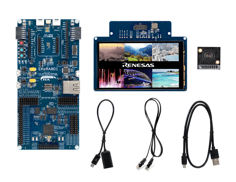
The EK-RA8D1 kit consists of three boards: the EK-RA8D1 board featuring the RA8D1 MCU with on-chip graphics LCD controller, a MIPI graphics expansion board featuring a 4.5-inch TFT color LCD (480 x 854) with capacitive touch overlay, and a camera expansion board featuring a 3M pixels CMOS image sensor.
Getting Started
Running the Quick Start Example Project
- The EK-RA8D1 board comes pre-programmed with a quick start example project (source code provided in the EK-RA8D1 example project bundle).
- Connect the MIPI graphics and camera expansion boards to the MIPI graphics (J58) and camera (J59) expansion ports on the EK-RA8D1 board.
- Power up the EK-RA8D1 board through the USB debug port (J10) using the micro USB device cable connected to a 5V power source. The white power LED will light up.
- The quick start example project will begin to execute showing the graphic elements on the screen.
- Refer to the EK-RA8D1 Quick Start Guide to explore additional functionality of the quick start example project.
Developing Embedded Applications
- Modifying the Quick Start example project – refer to the EK-RA8D1 Quick Start Guide for instructions on importing, modifying, and building the quick start example project.
- Start with one of the many other example projects (provided in the EK-RA8D1 example project's bundle) – choose from many example projects to learn about different peripherals of the RA8D1 MCU group. These example projects can serve as excellent starting points for you to develop your custom applications.
Building Custom Hardware
- Start by building a functional prototype - utilize the EK-RA8D1 board with your choice of ecosystem add-ons.
- Build custom hardware – develop custom hardware by referring to the design and manufacturing information provided in the EK-RA8D1v1 Design Package.
Features
- Special Feature Access:
- MIPI DSI and Parallel Graphics Expansion Ports
- Camera Expansion Port
- Ethernet
- USB High-Speed Host and Device
- 64MB SDRAM
- 64MB External Octo-SPI Flash
- MCU Native Pin Access:
- R7FA8D1BHECBD MCU
- 480MHz, Arm® Cortex®-M85 core
- 2MB Code Flash, 1MB SRAM
- 224 pins, BGA package, 13mm x 13mm x 1.47mm, 0.8mm pitch
- Native pin access
- MCU and USB current measurement
- DC/DC mode configuration
- Ecosystem and System Control Access:
- USB Full Speed Host and Device
- Multiple 5V input sources:
- USB (debug, full speed, high speed)
- External power supply
- SEGGER J-Link™ onboard programmer and debugger
- Debug modes:
- Debug onboard (SWD) – via J-Link
- Debug out (SWD) – via J-Link
- Debug in (ETM, SWD and JTAG) – via J-Link, Arm® Keil® ULINK™, IAR I-jet™, Renesas E2/E2 Lite, etc.
- User LEDs and buttons:
- Three user LEDs (red, blue, green)
- Power LED (white) indicating the availability of regulated power
- Debug LED (yellow) indicating the debug connection
- Two user buttons
- One reset button
- Five most popular ecosystem expansions:
- MikroElektronika™ mikroBUS connector
- SparkFun® Qwiic® connectors (may not be populated)
- Two SeeedGrove® system (I2C and analog) connectors (may not be populated)
- Two Digilent Pmod™ (SPI and UART) connectors
- Arduino® (UNO R3) connector
- MCU boot configuration
- MIPI Graphics Expansion Board:
- 4.5 Inch backlit TFT display, 16.7M display colors
- 480x854 pixels resolution
- 2-lane MIPI interface
- Capacitive touch overlay (I2C)
- Camera Expansion Board:
- Off-the-shelf Arducam CMOS OV3640 Camera Module
- ¼ Inch 3.1 Megapixel image sensor
- Up to 15 fps in QXGA (2048x1536 pixels) resolution
Applications
Documentation
|
|
|
|
|---|---|---|
| Type | Title | Date |
| Quick Start Guide | PDF 39.73 MB 日本語 | |
| Manual - Development Tools | PDF 2.86 MB 日本語 | |
| PCB Design Files | ZIP 249.98 MB | |
| Tool News - Release | PDF 229 KB 日本語 | |
| Application Note |
PDF
748 KB
The EK-RA8D1 example project bundle demonstrates how to write code for various Renesas Flexible Software Package (FSP) modules supported by the EK-RA8D1 kit. It includes multiple example projects that highlight peripheral usage and system functionality, while leveraging the optimized, scalable, and high‑quality FSP for embedded system design.
|
|
| Application Note | Reference System Design for Vision AI on EK-RA8D1
Learn how the Renesas RA8 Series MCUs integrate Helium technology which boosts performance when running an Artificial Intelligence (AI) model. There are other supporting hardware features that can be used in an AI application project.
|
|
| Quick Start Guide |
PDF
5.58 MB
日本語
The Modbus protocol stack operates on RA evaluation boards to enable efficient development of Modbus TCP applications. This quick start guide provides an overview of the protocol stack features and introduces a Modbus sample application to assist with the development and implementation of applications using the stack.
|
|
| Application Note |
PDF
2.60 MB
Learn how to implement an embedded webcam solution in the Renesas RA8 MCU, featuring an integrated Camera Engine Unit (CEU) and advanced networking capabilities.
|
|
| Application Note |
PDF
3.27 MB
Introduces the MCU boot firmware features and tool support to utilize Secure Factory Programming (SFP) for RA8 MCUs. Guidelines and procedures for utilizing these features and tools are provided. This application note also provides the key operations during SFP, Firmware Image Encryption and Device Lifecycle Management (DLM). This application note provides usage notes on how to use SFP with solutions such as the First Stage Bootloader (FSBL), TrustZone, and Decryption On The Fly (DOTF).
|
|
| Application Note |
PDF
3.87 MB
Presents the development of a graphics application for the RA8D1 MCU using the MIPI display on the EK-RA8D1 evaluation kit. This application note explains GUI design with SEGGER AppWizard and integration with e² studio using RA FSP, emWin, and FreeRTOS. The note also covers touch panel interfacing and discusses key design tradeoffs for optimizing graphics performance on the RA8D1 architecture.
|
|
| Application Note |
PDF
2.35 MB
Learn how to inject plaintext keys into RA MCUs using various security engines operating in Compatibility Mode. This application note details the protection of the Root of Trust, emphasizing secure key storage through hardware unique keys (HUK) and isolated cryptographic operations within the security engine. The security engines support multiple cryptographic algorithms and key handling methods, enabling secure and efficient key management.
|
|
| Tool News - Release |
PDF
150 KB
日本語
This is a Tool News announcing the revision of QE for Motor V1.5.1, Development Assistance Tool for Motor Applications.
QE for Motor is a development support tool that supports the development of embedded systems for motors that can be tuned and analyzed in conjunction with Renesas Motor Workbench, in addition to configuring the motor middleware and related drivers of Renesas microcontrollers.
The main revision upgrades is support for MCK-RA6T2 Version 2.
|
|
| Tool News - Release |
PDF
353 KB
日本語
This is a Tool News announcing the revision of QE for Camera[RA] V1.2.0, Development Assistance Tool for Camera Applications.
This development assistance tool supports the development of embedded systems which use the camera functions of display controllers from Renesas.
The main revision upgrades include support for the new device RA8D2 and support for MIPI PHY, MIPI CSI interface, and video input module (VIN).
|
|
| Tool News - Release |
PDF
153 KB
日本語
This is the Tool News announcing the revision upgrade to QE for Display [RX,RA] V3.7.0, Development Assistance Tool for Display Applications.
QE for Display [RX,RA] is a development assistance tool that supports the development of embedded systems using the LCD display functions of display controllers from Renesas.
With this revision upgrade, the tool now supports the new device RA8D2.
|
|
| Manual - Development Tools |
PDF
471 KB
日本語
Renesas RA8 MIPI Graphics Expansion Board 1 v1 adds high-resolution LCD and capacitive touch functionality to RA8 MCU evaluation kits via a 2-lane MIPI DSI interface. It features a 4.5-inch 480×854 TFT display and PWM-controlled backlight, and complies with global EMC and safety standards—ideal for embedded display applications in lab environments.
|
|
| Application Note |
PDF
402 KB
AI-generated Summary:
The document explains the two operational modes, highlighting their advantages and disadvantages, and provides practical guidance for selecting and using each mode. It also includes reference links to Renesas RA Family Application Projects that demonstrate these modes with detailed examples of the related FSP module usage.
|
|
| Application Note |
PDF
4.24 MB
Learn how to effectively interface with the boot mode on Renesas RA Family MCUs through practical examples and guidance. This application note builds on the official boot mode interface specifications (such as those for RA8M1 and RA8P1) to provide hands-on insights from both hardware and software perspectives. It helps developers understand the process of accessing boot mode on these devices, making it easier to implement and troubleshoot boot mode features in their applications.
|
|
| Manual - Development Tools |
PDF
646 KB
日本語
The Parallel Graphics Expansion Board 1 v1 features a high-resolution 7-inch capacitive touch display and 2 options for LCD connectivity, empowering developers to quickly prototype and showcase embedded applications with stunning visuals.
|
|
| PCB Design Files | Parallel Graphics Expansion Board 1 v1 for EK-RA8xx - Design Package
The design data includes the schematic, BOM, PCB layout files, and Gerber artwork for the parallel graphics expansion board which is compatible with the EK-RA8D2 and EK-RA8P1 kits.
|
|
| Tool News - Release | PDF 152 KB 日本語 | |
| Tool News - Release | PDF 152 KB 日本語 | |
| PCB Design Files | MIPI Graphics Expansion Board 1 v1 for EK-RA8xx - Design Package
|
|
| Manual - Development Tools | PDF 600 KB | |
| Application Note |
PDF
4.13 MB
AI-generated Summary:
The document details a DSP design workflow for creating an Audio Equalizer using MATLAB Filter Design tools and CMSIS-DSP libraries optimized for Renesas RA8 MCUs with Arm Cortex-M85 cores. It covers filter design, source code generation, project building, and execution on hardware such as the EK-RA8D1 evaluation kit and WM8960 audio codec. The workflow includes software tools like e2 studio, LLVM toolchain, and optional MATLAB and Segger SystemView. It explains how to optimize DSP performance using Arm Helium extensions and provides step-by-step instructions for hardware setup, software configuration, and latency measurement. The project supports RA8D1 and other RA MCUs with SSIE interfaces.
|
|
| Tool News - Release | PDF 335 KB 日本語 | |
| Tool News - Release | PDF 169 KB 日本語 | |
| Application Note |
PDF
2.58 MB
AI-generated Summary:
The RA8 MCU Quick Design Guide details essential design considerations for Renesas RA8 microcontrollers, covering power supply configurations, emulator interfaces, operating modes, memory architecture, clock circuits, reset mechanisms, security features, and I/O port configurations. It highlights dual power domains, switching regulator connections, USB and MIPI interface power pins, and capacitor placement for stable operation. The guide also explains emulator support via SWD and JTAG, clock frequency requirements for peripherals, reset source determination, TrustZone security implementation, memory protection, and low power consumption strategies. It serves as a practical reference to accelerate development and ensure robust hardware design.
|
|
| Application Note |
PDF
13.23 MB
AI-generated Summary:
Develop a multi-threaded touchscreen thermostat application using Renesas RA MCUs with Azure RTOS GUIX and FSP. Configure MIPI LCD display, touch drivers, and RTOS objects to enable a responsive graphical user interface. Utilize e2 studio IDE and Azure RTOS GUIX Studio for project creation, integration, and debugging. Control hardware features like PWM backlight and handle system events efficiently. The package includes step-by-step procedures for setup, building, running, and testing the application on EK-RA8D1 hardware with MIPI LCD.
|
|
| Application Note |
PDF
5.25 MB
AI-generated Summary:
The document guides the development of a multi-threaded thermostat application with a touch screen GUI using Renesas RA MCUs, Azure RTOS GUIX, and the Flexible Software Package (FSP). It covers setting up the parallel LCD display, integrating touch drivers, managing hardware access, and implementing system updates and event handling. The guide includes steps for project creation, enabling SDRAM for GUIX storage, configuring timers for backlight control, and debugging. It supports rapid development of connected IoT devices with secure, production-ready drivers and middleware stacks such as Ethernet and USB. The package includes PCB design files like BOM, schematics, and Gerber files for hardware integration.
|
|
| Application Note |
PDF
3.26 MB
AI-generated Summary:
MCUboot provides a secure bootloader infrastructure for 32-bit MCUs, enabling secure booting and fail-safe application updates. It supports multiple update strategies including Overwrite, Swap, and Direct Execute-In-Place (DXIP), each with distinct advantages and trade-offs. The bootloader authenticates firmware images using RSA or ECDSA signatures and SHA-256 hashing. Integration with Renesas RA Family MCUs via the Flexible Software Package (FSP) facilitates secure application design using TrustZone technology. Example projects demonstrate usage on EK-RA8M1 hardware with internal flash, supporting various update modes and cryptographic signing tools. The document guides developers through project setup, bootloader creation, application signing, and lifecycle management for secure embedded system development.
|
|
| Application Note |
PDF
1.37 MB
AI-generated Summary:
The Renesas RA8 MCU with Arm® Cortex®-M85 core and Helium™ technology delivers enhanced performance for DSP and machine learning applications. It leverages Single Instruction Multiple Data (SIMD) via Helium™ vector extensions, supporting both integer and floating-point operations. The MCU runs up to 480 MHz, featuring up to 2 MB flash, 1 MB SRAM with Tightly Coupled Memory (TCM), and advanced peripherals like Ethernet, USB, and security functions. Performance improvements utilize TCM, data caches, and optimized toolchains including LLVM and Renesas Flexible Software Package. The document includes application examples demonstrating vector multiply-accumulate instructions and benchmarking results to highlight performance gains.
|
|
| Flyer | PDF 412 KB | |
| Application Note |
PDF
35.58 MB
日本語
AI-generated Summary:
The document guides users through creating a two-screen GUI application using Azure RTOS GUIX Studio on the EK-RA8D1 kit. It covers setting up the MIPI display controller, touch screen driver, and semaphores for task communication. The guide includes project creation, driver configuration, GUI design, and basic debugging using Renesas Flexible Software Package (FSP) with Azure RTOS ThreadX and GUIX libraries. Required tools include e2 studio IDE, FSP v5.1.0+, and GUIX Studio v6.3.0.1+. The bundled software files include source code for touch drivers and system threads. The document supports rapid embedded GUI development with touch interaction on Renesas RA MCUs.
|
|
| Tool News - Release | PDF 413 KB 日本語 | |
| Tool News - Release | PDF 266 KB 日本語 | |
| Application Note |
PDF
20.47 MB
日本語
AI-generated Summary:
Create a simple two-screen GUI using Azure RTOS GUIX Studio for the EK-RA8D1 kit. Configure the Renesas Flexible Software Package (FSP), which integrates Azure RTOS ThreadX, GUIX library, and hardware drivers, to enable rapid embedded application development. Set up GLCD controller, touch screen driver, and semaphores for task communication. Develop the project in e2 studio with FSP v5.1.0 and GUIX Studio v6.2.1.0. The application responds to touch inputs, demonstrating basic GUI functionality. The package includes source code files and instructions for hardware setup, project creation, and debugging. Download tools and install required software versions before starting development.
|
|
| Presentation | PDF 7.02 MB | |
| Presentation | PDF 5.18 MB | |
| Application Note |
PDF
5.19 MB
AI-generated Summary:
The document explains how to optimize memory usage in RA8 MCUs by detailing internal Flash and SRAM architectures and external memory interfaces such as OSPI and SDRAM. It covers configuring standby SRAM and Tightly Coupled Memory (TCM), and explains ECC and parity memory features. The RA8 bus architecture supports efficient communication between CPU, memory, and peripherals using AMBA protocols. It describes bus masters and slaves, their roles, and synchronization. The document also guides system memory design, low power memory operation, and configuration using the Flexible Software Package (FSP).
|
|
| Flyer | PDF 402 KB 日本語 | |
| Report | PDF 187 KB 日本語 | |
41 items
|
||
Design & Development
Software & Tools
Software & Tools
| Software title
|
Software type
|
Company
|
|---|---|---|
| Edge AI Solutions for Automotive Safety & Intelligent Monitoring Provides in‑cabin safety and monitoring solutions using NPU compatible technology to enhance vehicle safety during operation. Supports real‑time vision‑based analytics such as driver monitoring and crowd counting, optimized for Renesas RZ/V2H MPU with the DRP-AI3 accelerator to achieve high accuracy with low-power consumption. NetsPresso® enables hardware‑aware AI optimization and deployment on Renesas RA8D1 and RA8P1 MCUs and RZ/V MPUs, allowing developers to build lightweight and efficient AI applications.
|
AI | Nota AI |
| PALMiCE4 PALMiCE4 is a professional JTAG emulator designed for microprocessors (MPUs) and microcontrollers (MCUs) based on Arm® Cortex®‑A, Cortex‑R, and Cortex‑M cores. It supports Arm CoreSight™ and Serial Wire Debug (SWD) interfaces, enabling multi‑core debugging, on‑board flash programming, and debugging in Arm TrustZone® environments. Broad device support includes the RZ MPU and RA MCU families, providing efficient software development from MCUs to SoC and multi‑core MPU platforms.
|
Development Tool | Computex Co., Ltd. |
| Plumerai AI Solution Plumerai delivers a complete on-device AI solution for cameras, running efficiently on both MCUs and MPUs. It combines motion detection, people, vehicle, animal, and package detection, Familiar Face Identification, and AI Video Search in one deployable and scalable stack. Built for real-world products, Plumerai helps camera makers add accurate, low-power, privacy-friendly AI directly on-device, reducing cloud dependence while enabling advanced features across entry-level and higher-performance platforms.
|
AI | Plumerai |
| QuickConnect Platform QuickConnect platform enables fast prototyping by providing compatible hardware and software building blocks.
|
Software and Hardware Development Tools | Renesas |
| RA Flexible Software Package (FSP) FSP is an enhanced software package designed to provide easy-to-use, scalable, high-quality software for embedded system designs using Renesas RA Family of Arm Microcontrollers.
Note: FSP with e² studio Installer (Platform Installer) will install the e² studio tool, FSP packs, GCC toolchain, and Segger J-Link drivers required to use this software. No additional installations are required.
|
Software Package | Renesas |
| Renesas AI Model Deployer for Vision AI The Renesas AI Model Deployer is an intuitive graphical user interface (GUI) tool integrated with NVIDIA’s powerful TAO Toolkit.
|
Solution Toolkit | Renesas |
| Renesas Flash Programmer (Programming GUI) Flash memory programming software [Support MCU/MPU and devices: RA, RE, RX, RL78, RH850, RISC-V MCU, Renesas Synergy, DA1453x, DA1459x, DA1469x, DA1470x, DA148xx, Power Management, Renesas USB Power Delivery Family, ICs for Motor Driver/Actuator Driver, V850, 78K0R, 78K0]
|
Programmer (Unit/SW) | Renesas |
| Scalable Embedded UI Platform for MCUs/MPUs LVGL is an embedded UI ecosystem that enables companies to build consistent user interfaces across their product portfolios. LVGL Open is a free, open source graphics library supporting 2D and 3D graphics on both MCUs and MPUs. LVGL Safe targets functional safety applications, while LVGL Pro provides professional UI development tools. With no royalties and a scalable architecture, LVGL allows OEMs to standardize UI development across products and teams while maintaining full control over their software stack.
|
HMI | LVGL |
| Slint Slint allows product teams to build modern user interfaces for any device. Slint tools enable teams to transform Figma designs into production-ready code and iterate quickly with live preview on target devices. With automated GUI testing in continuous integration and continuous delivery (CI/CD) pipelines, regressions and UI bugs can be detected early. Slint delivers efficient rendering for resource-constrained hardware and supports Rust, C++, JavaScript, and Python. Slint also offers Safety-critical graphics capabilities to support UI in systems requiring functional safety certification.
|
HMI | Slint |
| SquareLine Studio SquareLine Studio enables users to create visually impressive and high-performance UI interfaces for Renesas hardware quickly and efficiently.
|
HMI | SquareLine Kft |
10 items
|
||
Sample Code
Sample Code
Filters
|
||
|---|---|---|
| Type | Title | Date Date |
| Sample Code | EK-RA8D1 Example Project Bundle
The EK-RA8D1 example project bundle demonstrates how to write code for various Renesas Flexible Software Package (FSP) modules supported by the EK-RA8D1 kit. The sample code provides ready‑to‑build reference implementations that illustrate peripheral operation and system behavior, enabling developers to quickly evaluate FSP features and accelerate embedded application development.
|
|
| Sample Code | Reference System Design for Vision AI on EK-RA8D1
|
|
| Sample Code | RA Family Modbus Sample Program Package
Use the following sample program to operate on the RA evaluation board. This sample program package supports the Ethernet-based Modbus TCP protocol.
|
|
| Sample Code | RA8 CEU Webcam Getting Started Guide
Learn how to implement an embedded webcam solution in the Renesas RA8 MCU, featuring an integrated Camera Engine Unit (CEU) and advanced networking capabilities.
|
|
| Sample Code | Develop Graphics Applications Using the MIPI DSI Interface on the RA8D1
Provides sample code for the development of a graphics application for the RA8D1 MCU using the MIPI display on the EK-RA8D1 evaluation kit.
|
|
| Sample Code | Injecting Plaintext User Keys
Learn how to inject plaintext keys into RA MCUs using security engines operating in Compatibility Mode. Example projects for various MCUs and security engines demonstrate plaintext key injection with Renesas Flexible Software Package (FSP) APIs and PSA Certified Crypto APIs.
|
|
| Sample Code | Implementing Production Programming Tools for RA Cortex-M85 with Device Lifecycle Management
The accompanying demo code, provided in Python, demonstrates how to access and interact with the boot mode on RA8M1 and RA8P1 MCUs. It serves as a practical example for developers to see the boot mode interface in action, showing step-by-step procedures for communication and control. Although targeted at RA8M1 and RA8P1, the code and methodology can be adapted to other RA8 MCU devices by following the guidelines laid out in the application note, thereby accelerating development and reducing errors when working with boot mode features.
|
|
| Sample Code | RA6 Secure Bootloader Using MCUboot with Protected mode and Internal Code Flash
Learn how to create an application project using the MCUboot Module in Protected Mode on the Renesas EK-RA6M4 board with FSP v6.1.0. The intended audience includes product developers, product manufacturers, product support, and end users who are involved in designing application systems involving the use of a secure bootloader.
|
|
| Sample Code | "GUIX Thermostat" for EK-RA8D1 MIPI Display
|
|
| Sample Code | "GUIX Thermostat" for EK-RA8D1 Parallel GLCD Display
|
|
| Sample Code | High Performance with RA8 MCU using Arm® Cortex®-M85 core with Helium™
|
|
| Sample Code | GUIX Hello World for EK-RA8D1 MIPI LCD Display
|
|
| Sample Code | GUIX "Hello World" for EK-RA8D1 - Sample Code
|
|
13 items
|
||
Related Boards & Kits
Boards & Kits

Evaluation Kit for RA8M1 MCU Group
The EK-RA8M1 evaluation kit enables users to effortlessly evaluate the features of the RA8M1 MCU Group and develop embedded systems applications using Renesas' Flexible Software Package (FSP) and e2 studio IDE. Utilize rich onboard features along with your choice of popular ecosystem add-ons to... Read More
Product Options
| Part Number | Status | Stock | Budgetary Price (USD) | Sampleable |
|---|---|---|---|---|
| RTK7EKA8D1S01001BE | Active | In Stock | 1u | $326 | Available |
Videos & Training
Learn how to access data flash on the RA8D1 Evaluation Kit by performing erase, blank check, write, and read operations using the Flexible Software Package (FSP). We demonstrate how data flash background operation (BGO) enables execution from code flash during programming and erase. We also explain secure and non‑secure data flash access using Arm® TrustZone® technology. The project shows how flash management supports reliable and secure embedded system design.
Additional Videos
News & Blog Posts
News Dec 12, 2023 |
Blog Post Dec 12, 2023 |
Blog Post Jan 28, 2022 |
Blog Post Jan 28, 2022 |
Blog Post Nov 18, 2021 |
Blog Post Nov 11, 2021 |
Certifications
The EK-RA8D1 kit meets the following certifications/standards. Refer to the EK-RA8D1 user manual for the disclaimer, precautions and more details on the certifications.
EMC/EMI Standards
- FCC Notice (Class A) – Part 15
- Innovation, Science and Economic Development Canada ICES-003 Compliance: CAN ICES-3 (A)/NMB-3(A)
- CE Class A (EMC Directive 2004/108/EEC)
- Taiwan Chinese National Standard 13438, C6357 compliance, Class A limits
- Australia/New Zealand AS/NZS CISPR 32:2015, Class A
Material Selection, Waste, Recycling, and Disposal Standards
- EU RoHS
- China SJ/T 113642014, 10-year environmental protection use period
Safety Standards
- UL 94V-0
Partners

Zephyr Project
The Zephyr Project is an open-source, scalable real‑time operating system (RTOS) designed for resource-constrained embedded systems and supports a wide range of hardware architectures and development boards. For the Renesas RA8D1 Evaluation Kit, Zephyr provides focused documentation covering board features, supported peripherals, and basic build, flashing, and debugging workflows to help developers quickly get started.
Support
Support Communities
- Getting Started with EK-RA8D1-Graphics Application Embedded Wizard
Materials for Getting Started with EK-RA8D1-Graphics Application Embedded Wizard on EK-RA8D1 and FSP 5.5.0.
- InvocationTargetException when I create a new Example Hello World Project with EK-RA8D1
... of times but i can't seem to go past this error. I'm following exact steps listed in the example projects of RA8D1 and EK-RA8D1. Even if I ignore the error, I'm unable to save anything in configuration.xml file. I'm not sure if they are ...
May 24, 2025 - LVGL in EK-RA8D1
EK-RA8D1 with LVGL example project This thread was automatically locked due to age.
Aug 28, 2024
Knowledge Base
- RA and FSP Curriculum : Getting Started with EK-RA8D1 Graphics Application Embedded Wizard
Last Updated: 30 Oct 2024 This lab material explains all necessary steps to create an Embedded Wizard UI application suitable for RA8D1 Evaluation Kit. Getting Started with EK-RA8D1 Graphics Application Embedded Wizard for FSP 5.5.0 - a hands on lab using EK-RA8D1, Embedded Wizard Studio and FSP ...
Oct 30, 2024 - How to Use ADC to Read On‑Chip Temperature Sensor on RA8D1 Evaluation Kit
Last updated on 1st June 2026 Summary of the video This video demonstrates how to measure the internal MCU temperature on the EK-RA8D1 board using the ADC temperature sensor. Flexible Software Package (FSP) supports ADC operation with the r_adc FSP module. This example demonstrates configuring the ADC with ...
- How to Access Data Flash on RA8D1 Evaluation Kit
Last updated on 1st June 2026 Summary of the video This video demonstrates how to perform basic Data Flash operations on the EK-RA8D1 board using the Flash HP driver. Flexible Software Package (FSP) supports Data Flash erase, blank check, write, and read operations with the r_flash_hp FSP ...

Support Communities


