
Overview
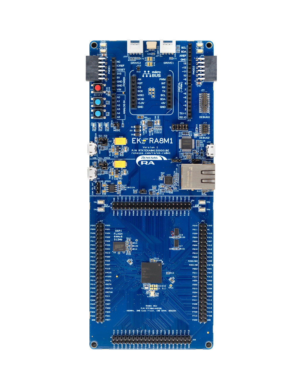
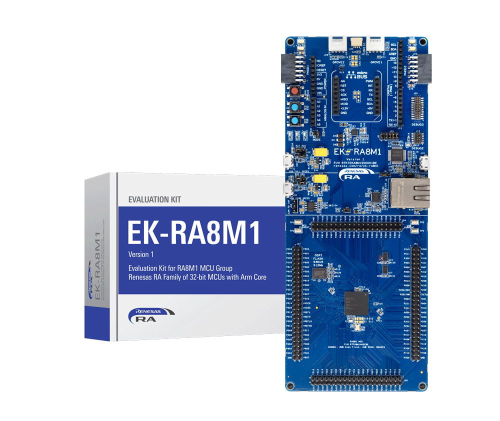
The EK-RA8M1 evaluation kit enables users to effortlessly evaluate the features of the RA8M1 MCU Group and develop embedded systems applications using Renesas' Flexible Software Package (FSP) and e2 studio IDE. Utilize rich onboard features along with your choice of popular ecosystem add-ons to bring your big ideas to life.
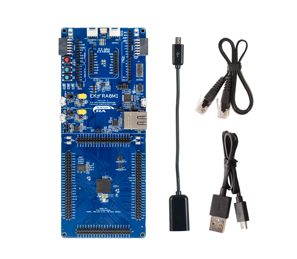
The kit includes the EK‑RA8M1 board, Micro USB device and host cables (Type‑A to Micro‑B), and an Ethernet patch cable.
Getting Started
Running the Quick Start Example Project
- The EK-RA8M1 board comes pre-programmed with a quick start example project (source code provided in the EK-RA8M1 example project bundle).
- Power up the EK-RA8M1 board through the USB debug port (J10) using the micro USB device cable connected to a 5V power source. The white power LED will light up.
- The quick start example project will begin to execute blinking the blue user LED.
- Refer to the EK-RA8M1 - Quick Start Guide (PDF | English, 日本語) to explore additional functionality of the quick start example project.
Developing Embedded Applications
- Modifying the quick start example project – refer to the EK-RA8M1 Quick Start Guide for instructions on importing, modifying, and building the quick start example project.
- Start with one of the many other example projects (provided in the EK-RA8M1 example project's bundle) – choose from many example projects to learn about different peripherals of the RA8M1 MCU group. These example projects can serve as excellent starting points for you to develop your custom applications.
Building Custom Hardware
- Start by building a functional prototype - utilize the EK-RA8M1 board with your choice of ecosystem add-ons.
- Build custom hardware – develop custom hardware by referring to the design and manufacturing information provided in the EK-RA8M1 v1 - Design Package (ZIP).
Features
- Special Feature Access:
- Ethernet
- USB High-Speed Host and Device
- 64MB External Octo-SPI Flash
- CAN FD PHY
- MCU Native Pin Access:
- R7FA8M1AHECBD MCU
- 480MHz, Arm® Cortex®-M85 core
- 2MB Code Flash, 1MB SRAM
- 224 pins, BGA package, 13mm x 13mm x 1.47mm, 0.8mm pitch
- Native pin access
- MCU and USB current measurement
- DC/DC mode configuration
- Ecosystem and System Control Access:
- USB full speed host and device
- Multiple 5V input sources:
- USB (debug, full speed, high speed)
- External power supply
- SEGGER J-Link™ onboard programmer and debugger
- Debug modes:
- Debug onboard (SWD) – via J-Link
- Debug out (SWD) – via J-Link
- Debug in (ETM, SWD and JTAG) – via J-Link, Arm® Keil® ULINKTM, IAR I-jetTM, Renesas E2/E2 Lite, etc.
- User LEDs and buttons:
- Three user LEDs (red, blue, green)
- Power LED (white) indicating the availability of regulated power
- Debug LED (yellow) indicating the debug connection
- Two user buttons
- One reset button
- Five most popular ecosystem expansions:
- MikroElektronika™ mikroBUS connector
- SparkFun® Qwiic® connector
- Two SeeedGrove® system (I2C and analog) connectors
- Two Digilent Pmod™ (SPI and UART) connectors
- Arduino™ (Uno R3) connector
- MCU boot configuration
Getting Started
Explore Ready-to-Run Solutions
Sample & Buy

Evaluation Kit for the RA8M1 MCU Group
| Description: | Evaluation Kit for the RA8M1 MCU Group |
| HTS (US): | 8471.50.0150 |
| ECCN (US): | 3A991.a.2 |
| SPQ: | 1 |
| Pb (Lead) Free: | No |
| Assembly Location: | CHINA |
Videos & Training
The industry’s first high-performance MCUs based on the new Arm® Cortex®-M85 core with Helium are ideal for compute-intensive DSP and AI/ML tasks. The RA8M1 delivers 480MHz with up to 2MB code flash memory, 1MB SRAM and advanced peripherals.
Additional Videos
News & Blog Posts
News Oct 31, 2023 |
Blog Post Oct 31, 2023 |
Blog Post Jan 28, 2022 |
Blog Post Jan 28, 2022 |
Blog Post Nov 18, 2021 |
Blog Post Nov 11, 2021 |
Support
Support Communities
- EK-RA8M1, using SCI1 as a slave in simple SPI mode
We have tried to use SCI1. Regardless of the position of J61, we did not succeed.During the analysis, we found that the documentation of the EK-RA8M1 does not match the schematic.According to the schematic, J61 must be opened to activate Ethernet B.According to the description, J61 ...
Oct 9, 2025 - Programming external memory in EK-RA8M1 Evaluation kit
I am currently using EK-RA8M1 evaluation kit for one of my project. For my project requirement, I need to store sound file in the external memory. As per the data sheet, the evaluation kit has *** MB external memory (S28HL512TFPBHI010) and which connected to OSPI pins. I want to store ...
May 12, 2026 - How to enable trace on EK-RA8M1 board with Keil MDK IDE and J-Trace?
I'm trying to enable the trace on EK-RA8M1 board with Keil MDK IDE and J-Trace. But once the trace is enabled in the Keil/debug/trace setting, the J-trace is no longer able to connect to the RA8M1. The message says "Failed to power ...
Sep 18, 2024
Knowledge Base
- RA Family: How to generate self-signed x509 certificate using MbedTLS stack
Last Updated: 02/04/2025 Answer: The attached sample reference application generates an RSA self-signed x509 certificate by leveraging FSP middleware MbedTLS stack and RSIP IP of RA on the EK-RA8M1 board. Below are the list of operations that can be verified using the sample application ...
Feb 4, 2025 - RA Family: IP Port forwarding from RNDIS based USBX Ethernet to IPv4 Ethernet Port
... router To simulate this setup, this article describes the steps required to configure IP forwarding on an RA8M1 MCU running Azure ThreadX RTOS, using the EK-RA8M1 evaluation kit as an example. The configuration establishes IP forwarding between an RNDIS-based Ethernet interface connected to a Windows system and a ...
May 18, 2026 - RA and FSP Curriculum: I-002A Fundamentals of FSP (Non-Trustzone)
... are available in a single zip file located here. I-002A Fundamentals of FSP Presentation and Lab (Non-TrustZone) for FSP 5.2.0 with EK-RA8M1- a step by step PPT hands-on lab using FSP 5.2.0 and the EK-RA8M1 kit. It introduces FSP including components ...
May 19, 2026

Support Communities

