
Overview
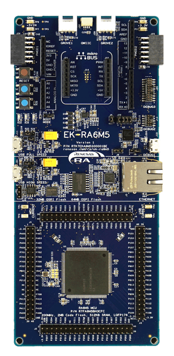
The EK-RA6M5 evaluation kit enables users to effortlessly evaluate the features of the RA6M5 MCU Group and develop embedded systems applications using the Flexible Software Package (FSP) and e2 studio IDE. Utilize rich on-board features along with your choice of popular ecosystem add-ons to bring your big ideas to life.
Getting Started
Running the Quick Start Example Project
- The EK-RA6M5 comes pre-programmed with a quick start example project (source code provided in the EK-RA6M5 Example Project Bundle).
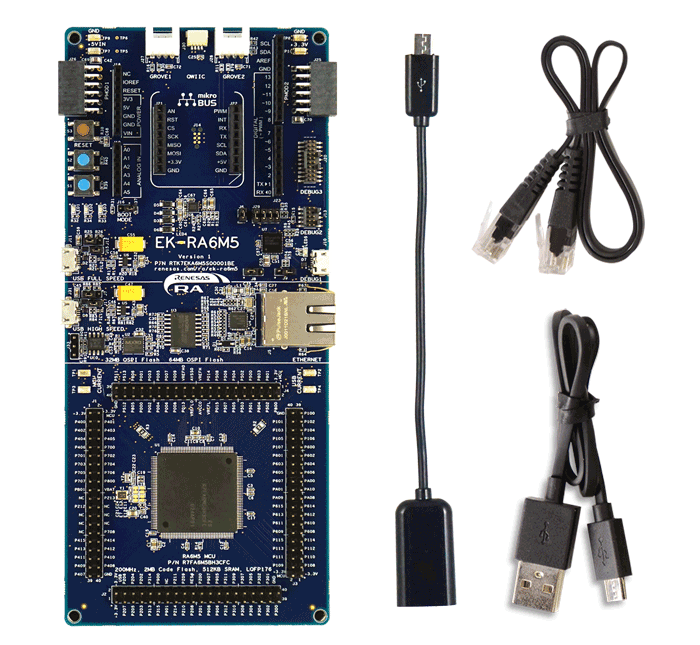
- Power up the EK-RA6M5 board through the debug USB port (J10) using the micro USB device cable connected to a 5V power source. The white power LED will light up.
- The quick start example project will begin to execute blinking the blue user LED.
- Refer to the EK-RA6M5 Quick Start Guide to explore additional functionality of the quick start example project.
Developing Embedded Applications
- Modifying the quick start example project – refer to the EK-RA6M5 Quick Start Guide for instructions on importing, modifying, and building the quick start example project
- Start with one of the many other example projects – choose from many example projects provided in the EK-RA6M5 Example Project Bundle to learn about different peripherals of the RA6M5 MCU Group. These example projects can serve as excellent starting points for you to develop your custom applications.
Building a Custom Hardware
- Start by building a functional prototype – utilize the EK-RA6M5 board with your choice of hundreds of popular ecosystem add-ons.
- Build custom hardware – develop custom hardware by referring to the design and manufacturing information provided in the EK-RA6M5 Design Package.
Features
- Ecosystem & System Control Access
- USB full speed host and device
- Multiple 5V input sources
- USB (debug, high speed, full speed)
- External power supply
- SEGGER J-LinkTM on-board programmer and debugger
- Debug modes
- Debug on-board (SWD) – via J-Link
- Debug out (SWD) – via J-Link
- Debug in (ETM, SWD & JTAG) – via J-Link, Arm® Keil® ULINKTM, IAR I-jetTM, Renesas E2/E2 Lite, etc.
- User LEDs and buttons
- Three user LEDs (red, blue, green)
- Power LED (white) indicating availability of regulated power
- Debug LED (yellow) indicating the debug connection
- Two user buttons
- One reset button
- Five most popular ecosystem expansions
- MikroElektronikaTM mikroBUSconnector
- SparkFun®Qwiic®connector
- Two SeeedGrove®system(I2C and Analog) connectors
- TwoDigilent PmodTM(SPI and UART) connectors
- ArduinoTM(UNO R3) connector
- MCU boot configuration jumper
- Special Feature Access
- Ethernet (RMII and PHY)
- 64MB External Octo-SPI Flash
- 32MB External Quad-SPI Flash
- CAN FD
- USB High Speed host and device
- MCU Native Pin Access
- R7FA6M5BH3CFC MCU
- 200MHz, Arm Cortex®-M33 core
- 2MB Code Flash, 512kB SRAM
- 176 pins, LQFP package, 24mm x 24mm x 1.70mm, 0.5mm pitch
- Native pin access through 4x 40-pin male headers
- MCU and USB current measurement points
Getting Started
Explore Ready-to-Run Solutions
Sample & Buy

Evaluation Kit for RA6M5 MCU Group
| Description: | Evaluation Kit for RA6M5 MCU Group |
| HTS (US): | 8471.50.0150 |
| ECCN (US): | 3A991.a.2 |
| SPQ: | 1 |
| Pb (Lead) Free: | No |
| Assembly Location: | UNITED KINGDOM |
Add-on Hardware

Evaluation Kit for RA6M1 MCU Group

Evaluation Kit for RA6M2 MCU Group

Evaluation Kit for RA6M3 MCU Group

Evaluation Kit for RA6M4 MCU Group
Videos & Training
Learn how we access Octal SPI flash on the RA6M5 Evaluation Kit to perform data operations in multiple modes. We will outline how the Octal SPI peripheral communicates with external OctaFlash and OctaRAM devices, and demonstrate erase, write, and read operations in both SPI mode and Single OPI mode.
Additional Videos
News & Blog Posts
Blog Post Apr 5, 2022 |
Blog Post Jan 28, 2022 |
Blog Post Jan 28, 2022 |
Blog Post Nov 18, 2021 |
Blog Post Nov 11, 2021 |
Support
Support Communities
- EK-RA6M5 USBFS Module is not starting
Hi All, I am working on EK-RA6M5 board to develop the application for USB Host. FSP - 3.8.0 IDE - IAR I am not using the FSP APIs for USB development I am going to develop our own USB low level drivers. So, for that I am trying to ...
May 12, 2023 - EK-RA6M5 Ethernet Issues after update FSP3.3 to FPS3.6
After updating the AzureCloud project to FSP3.6 I am no longer able to DHCP an ip address. _nxe_ip_status_check(…) waits for ever. Never gets the needed_status == 2 I noted : FSP3.3 is using g_dhcp_client0 NetX Duo DHCP Ipv4 Client Statcks FSP3.6 is using ...
Mar 18, 2022 - EK-RA6M5 multiple definition fault when using 2 CAN channels
Hello everyone, When I try to use both CAN channel 0 and channel 1, I faced with the following problem. g_canfd_global_cfg is defined different thread header so I take "multiple definition" fault as expected. How can I handle this. Your help would be much appreciated. This thread ...
Aug 26, 2023
Knowledge Base
- RA Family: How to use the Debug Out function of J-Link OB on EK (Evaluation Kit)
... as EK-RA2E1, EK-RA2E2, EK-RA2L1, EK-RA2A1, etcEK-RA4M1、EK-RA4M2、EK-RA4M3、EK-RA4W1、EK-RA6M1、EK-RA6M2, EK-RA6M3, EK-RA6M4, EK-RA6M5, etc., all EKs come with J-Link OB (On-Board Debugger), which means that the user can evaluate, debug, and test the MCU ...
Dec 14, 2023 - RA6M4, RA6M5: CPU Performance Difference when C-/S-caches are on/off
... if C-cache is hit. For the C-Cache is missed while C-Cache operation is enabled, or C-cache is disabled, the read access is three cycles. Reference Attachments: Example project on EK-RA6M4 for above benchmark testing (below) Example project on EK-RA6M5 for above benchmark testing (below)
Dec 18, 2023 - How to Use Event Link Controller to Link Peripherals on RA6M5 Evaluation Kit
Last updated on 2nd June 2026 Summary of the video This video demonstrates how to use the Event Link Controller (ELC) to link the General PWM Timer (GPT) with the Analog-to-Digital Converter (ADC) on the EK-RA6M5 board. Flexible Software Package (FSP) supports event linking with the r ...

Support Communities

