
Overview
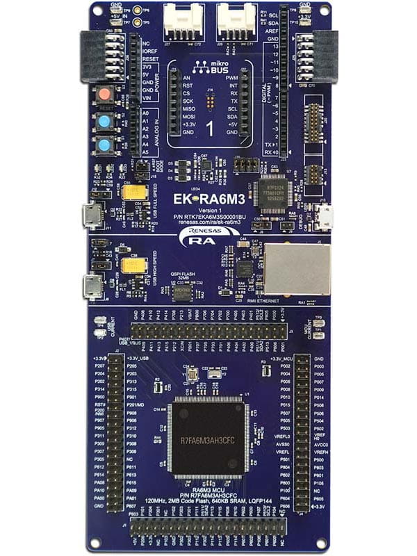
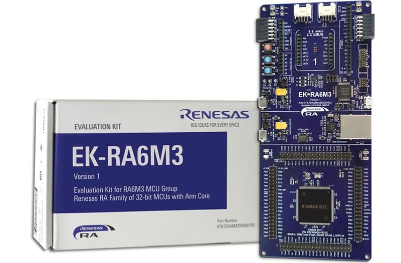
The EK-RA6M3 evaluation kit enables users to seamlessly evaluate the features of the RA6M3 MCU Group and develop embedded systems applications using the Flexible Software Package (FSP) and e2studio IDE. Utilize rich on-board features along with your choice of popular ecosystem add-ons to bring your big ideas to life.
Getting Started
Running the Quick Start Example Project
- The EK-RA6M3 comes pre-programmed with a quick start example project (provided with the example projects bundle).
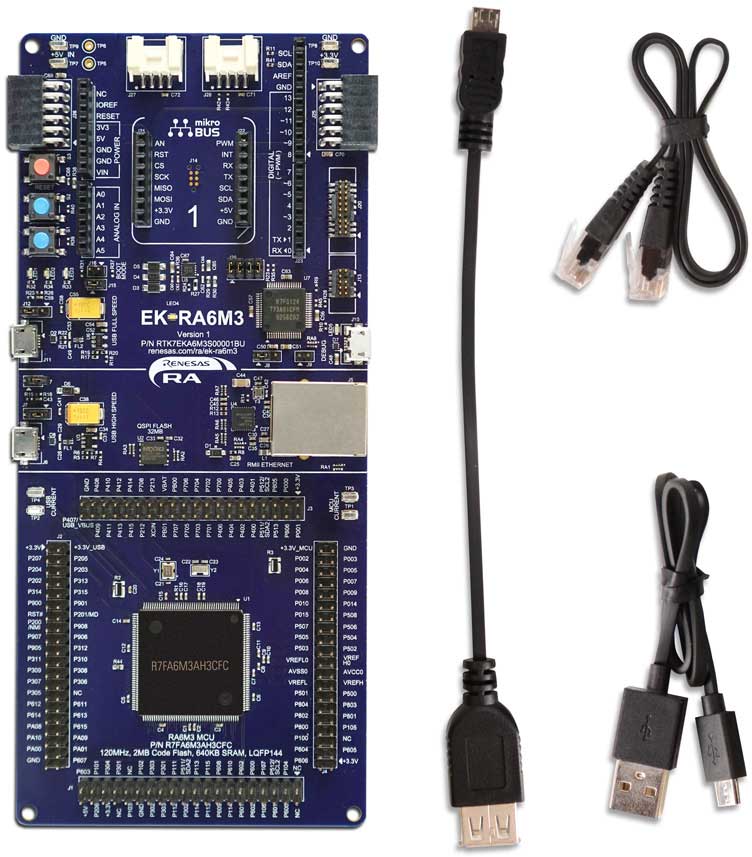
- Power up the EK-RA6M3 board through the debug USB port (J10) using the micro USB device cable connected to a 5V power source. The white power LED will light up.
- The quick start example project will begin to execute blinking the red, green and blue user LEDs.
- Refer to the EK-RA6M3 – Quick Start Guide (PDF | English, 日本語) to explore additional functionality of the quick start example project.
Developing Embedded Applications
- Modifying the quick start example project – refer to the EK-RA6M3 Quick Start Guide for instructions on importing, modifying, and building the quick start example project
- Start with one of the many other example projects (provided in the example projects bundle) – choose from many example projects to learn about different peripherals of the RA6M3 MCU Group. These example projects can serve as excellent starting points for you to develop your custom applications.
Building a Custom Hardware
- Start by building a functional prototype – utilize the EK-RA6M3 board with your choice of hundreds of popular ecosystem add-ons.
- Build custom hardware – develop custom hardware by referring to the design and manufacturing information provided in the EK-RA6M3 v1 - Design Package (ZIP | English, 日本語)
Features
- Special Feature Access
- Ethernet (RMII and PHY)
- USB High Speed host and device
- 32MB External QSPI Flash
- MCU Native Pin Access
- R7FA6M3AH3CFC MCU
- 120MHz, Arm Cortex®-M4 core
- 2MB Code Flash, 640kB SRAM
- 176 pins, LQFP package, 24mm x 24mm x 1.70mm, 0.5mm pitch
- Native pin access through 4x 40-pin male headers
- MCU and USB current measurement points
- Ecosystem & System Control Access
- USB Full Speed host and device
- Multiple 5V input sources
- USB (Debug, Full Speed, High Speed)
- External power supply
- SEGGER J-LinkTM on-board programmer and debugger
- Debug modes
- Debug On-board (SWD) – via J-Link
- Debug Out (SWD) – via J-Link
- Debug In (ETM, SWD & JTAG) – via J-Link, Arm® Keil® ULINKTM, IAR I-jetTM, Renesas E2/E2 Lite, etc.
- User LEDs and buttons
- Three user LEDs (red, blue, green)
- Power LED (white) indicating availability of regulated power
- Debug LED (yellow) indicating the debug connection
- Two user buttons
- One reset button
- Four most popular ecosystem expansions
- MikroElektronikaTM mikroBUSTM connector
- Two SeeedGrove® system (I2C) connectors
- Two Digilent PmodTM (SPI and UART) connectors
- ArduinoTM (Uno R3) connector
- MCU boot configuration jumper
Getting Started
Explore Ready-to-Run Solutions
Sample & Buy

Evaluation Kit for RA6M3 MCU Group
| Description: | Evaluation Kit for RA6M3 MCU Group |
| HTS (US): | 8471.50.0150 |
| ECCN (US): | 3A991.a.2 |
| SPQ: | 1 |
| Pb (Lead) Free: | No |
| Assembly Location: | CHINA |
Add-on Hardware

Evaluation Kit for RA6M1 MCU Group

Evaluation Kit for RA6M2 MCU Group

Evaluation Kit for RA6M4 MCU Group

Evaluation Kit for RA6M5 MCU Group
Videos & Training
Kickstart IoT and embedded systems development using Renesas EK-RA6M3, Evaluation Kit for RA6M3 MCU Group. Familiarize yourself with the kit architecture, key features, quick start example project and many useful resources to begin innovating quickly.
Additional Videos
News & Blog Posts
Blog Post Apr 5, 2022 |
Blog Post Jan 28, 2022 |
Blog Post Jan 28, 2022 |
Blog Post Nov 18, 2021 |
Blog Post Nov 11, 2021 |
Support
Support Communities
- setting up an MQTT stack on the EK-RA6M3 demo board
... you) for "RA AWS MQTT/TLS Cloud Connectivity Solution" instructions for setting up a MQTT stack, so I'm going through that on my EK-RA6M3 demo board. I am new to Renesas, and have only done a few "blinky" projects on my demo board, but the MQTT documentation ...
Jul 17, 2022 - I:002A Fundamentals of FSP (Non-Trustzone) FSP 420 EK-RA6M3
Material for presentation, lab and project files in a single zip
- EK-RA6M3 with US159-DA16600MEVZ Wi-Fi Quick-Connect IoT Provisioning Demo
Help Needed: Adapting EK-RA6M4 Project to EK-RA6M3 with DA16600EVZ WiFi Module - Error Code 0x00050004 Hello, I am currently working on a project using the EK-RA6M3 board with the DA16600EVZ WiFi module. My project is based on an existing example designed for the EK-RA6M4: Quick Connect IoT ...
Dec 19, 2023
Knowledge Base
- RA Family: How to use the Debug Out function of J-Link OB on EK (Evaluation Kit)
... this on-board debugger is officially provided by Renesas, and the firmware can be updated with the update of the SEGGER tool. In this article, EK-RA6M3 is used as an example to describe the specific implementation method. Refer to the schematic diagram of EK-RA6M3: J29 can be used ...
Dec 14, 2023 - Differences in Programming Speeds using J-Link PRO for RA6M4 and RA6M3 MCUs
... PRO, with e2studio 2021-04 (updated to the latest version of the J-Link DLL, v7.50) to program a 1088776 byte binary into the EK-RA6M3 with different SWD speeds set in the debug configuration:SWD 4000 :- ~5 seconds total time to download the program binarySWD 15000 :- ~3 seconds ...
Jul 6, 2021 - Quick FSP 0.8 Labs: Available Labs
... Lab is an EK-RA6M3 Evaluation Kit, along with e2 studio and FSP installed on your PC. You can find instructions for obtaining these here:EK-RA6M3 Kit Page: Here.EK-RA6M3 Ordering Information: Here. FSP and e2 studio Installation: Can be found on the GitHub FSP site. Current Quick ...

Support Communities

