Overview
Description
[Notes] Renesas Emulator and Flash Memory Programmer Products with a USB Interface Notice Regarding Changes to Windows Driver Policy (PDF | English, 日本語)
Topics
- The PG-FP6 supports the new device RX14T.
The PG-FP6 installed in a system is a tool for erasing, programming, and verifying programs on Renesas MCUs with on-chip flash memory.

Features
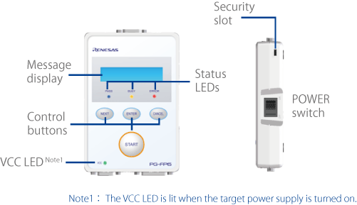
- Control panel suitable for stand-alone operation [Learn More]
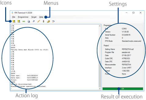
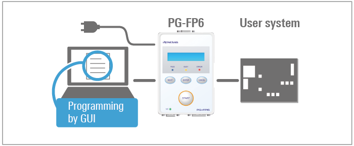
- Simple and user-friendly GUI, FP6 Terminal [Learn More]
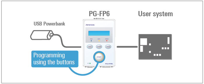
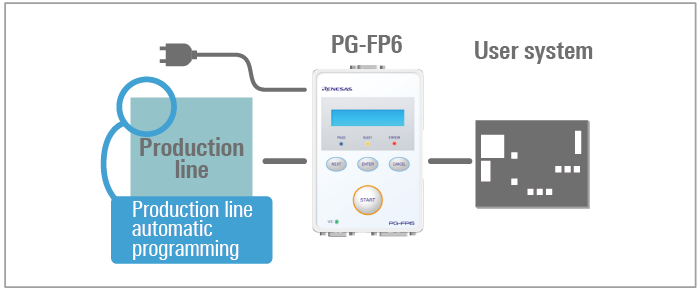
- Useful functions for production line: programming using by buttons and automatic programming
- Able to use USB power: convenient for programming in the field
- High-speed programming of MCUs by the PG-FP6 for reduced production times [Learn More]
- Support for high-volume programming by gang programming with the use of multiple PG-PF6s [Learn More]
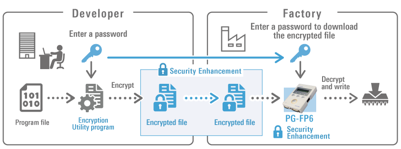
- Security Enhancement against theft of program files and the PG-FP6 main unit [Learn More]
- Security slot for theft prevention
- High-speed downloading of files for programming from a PC to the PG-FP6 [Learn More]
- Code storage capacity with 256MB for large flash memory
- High compatibility with the predecessor [Learn More]
Release Information
Programming GUI (FP6 Terminal)
Latest Ver. : V1.20.00
Released : Apr. 20, 2026
Note: The FP6 Terminal includes parameter files, firmware, and USB drivers.
Release information (See Tool News)
Operating Environment
FAQ
See also Error Guide.
Target Devices
Target Family
- RA Family
- RL78 Family
- RX Family
- RH850 Family
- RISC-V MCU
- Renesas Synergy™ Platform MCUs
- RE Family
- Power & Power Management (Battery Fuel Gauge ICs)
- Power & Power Management (USB Type-C & USB Power Delivery)
- Power & Power Management (Motor Control ICs)
- SuperH Family
- V850 Family Note1
- 78K Family Note1
- R8C Family
Note:
- Use programmers produced by partners for programming of the V850 and 78K with dual power supply flash memory, which assume mass production with mask ROM.
- For details of support for individual device part numbers, see List of MCUs supported by PG-FP6 (PDF | English, 日本語).
Downloads
|
|
|
|
|---|---|---|
| Type | Title | Date |
| Upgrade - Programmer | Programming GUI for PG-FP6 (FP6 Terminal) V1.20.00
|
|
|
1 item
|
||
Documentation
|
|
|
|
|---|---|---|
| Type | Title | Date |
| Manual - Development Tools |
PDF
2.41 MB
日本語
The PG-FP6 is a flash memory programmer for Mmicrocontrollers from Renesas Electronics. Stand-alone writing is supported. This manual describes Renesas Flash Programmer V3 functions, operations, troubleshooting, and precautions.
|
|
| Release Note |
PDF
597 KB
日本語
This document covers release information on the PG-FP6 products. It describes addition of supported devices, and improved functionality and change.
|
|
| Flyer | PDF 528 KB 日本語 , 简体中文 | |
| Manual - Development Tools |
PDF
206 KB
日本語
The PG-FP6 is a flash memory programmer for Mmicrocontrollers from Renesas Electronics. Stand-alone writing is supported. The microcontrollers, interfaces, and parameter files supported by Renesas Flash Programmer V3 are listed.
|
|
| Manual - Development Tools |
PDF
861 KB
日本語
The PG-FP6, Renesas Flash Programmer are flash memory programmer for Mmicrocontrollers from Renesas Electronics. This manual describes the recommended circuitry for connecting PG-FP6, Renesas Flash Programmer to the microcontroller.
|
|
| Tool News - Release | PDF 142 KB 日本語 | |
| Tool News - Release | PDF 140 KB 日本語 | |
| Tool News - Release |
PDF
142 KB
日本語
This is a tool news to announce the upgrade to revision to the Programming GUI for PG-FP6 Flash Memory Programmer (FP6 Terminal) V1.18.00.
It describes addition of supported devices, improved functionality and change, and updating the Product.
The main upgrade to revision are RL78/L23 group support, and increasing the speed of programming and verification via a FINE interface.
|
|
| Tool News - Release | PDF 143 KB 日本語 | |
| Tool News - Release | PDF 142 KB 日本語 | |
| Tool News - Note | PDF 148 KB 日本語 | |
| Tool News - Release | PDF 148 KB 日本語 | |
| Tool News - Release | PDF 143 KB 日本語 | |
| Tool News - Release | PDF 142 KB 日本語 | |
| Manual - Development Tools | PDF 662 KB 日本語 | |
| Tool News - Release | PDF 136 KB 日本語 | |
| Tool News - Release | PDF 145 KB 日本語 | |
| Tool News - Note | PDF 142 KB 日本語 | |
| Tool News - Release | PDF 137 KB 日本語 | |
| Tool News - Release | PDF 137 KB 日本語 | |
| Tool News - Release | PDF 137 KB 日本語 | |
| Tool News - Release | PDF 168 KB 日本語 | |
| Tool News - Featured Tool | PDF 864 KB 日本語 | |
| Tool News - Release | PDF 166 KB 日本語 | |
| Tool News - Notification | PDF 502 KB 日本語 | |
| Tool News - Release | PDF 161 KB 日本語 | |
| Manual - Development Tools | PDF 206 KB | |
| Tool News - Release | PDF 141 KB 日本語 | |
| Tool News - Release | PDF 156 KB 日本語 | |
| Tool News - Note | PDF 142 KB 日本語 | |
| Tool News - Release | PDF 90 KB 日本語 | |
| Tool News - Notification | PDF 92 KB 日本語 | |
| Tool News - Note | PDF 144 KB 日本語 | |
| Tool News - Release | PDF 139 KB 日本語 | |
| Tool News - Note | PDF 149 KB 日本語 | |
| Tool News - Release | PDF 137 KB 日本語 | |
| Tool News - Release | PDF 57 KB 日本語 | |
| Tool News - Featured Tool | PDF 193 KB 日本語 | |
| Tool News - Notification | PDF 306 KB 日本語 | |
| Tool News - Notification | PDF 304 KB 日本語 | |
| Tool News - Notification | PDF 352 KB 日本語 | |
| Tool News - Notification | PDF 29 KB 日本語 | |
| Tool News - Note | PDF 29 KB 日本語 | |
| Tool News - Release | PDF 72 KB 日本語 | |
| Application Note |
PDF
369 KB
日本語
AI-generated Summary:
Communications commands enable automated control and programming of Renesas microcontrollers and ICs via the PG-FP6 flash programmer using a serial interface. The document details the connection setup between the host PC, PG-FP6, and target system, creation of setting and macro files, and execution of commands through communications software. It supports various device families including RA, RL78, RX, RH850, and others. Procedures cover flash memory operations such as erasure, programming, and verification, with examples of multi-file and gang programming.
|
|
| Tool News - Note | PDF 105 KB 日本語 | |
| Tool News - Note | PDF 105 KB 日本語 | |
| Tool News - Note | PDF 118 KB 日本語 | |
| Tool News - Note | PDF 115 KB 日本語 | |
| Tool News - Release | PDF 384 KB 日本語 , 简体中文 | |
|
50 items
|
||
Design & Development
Product Options
| Part Number | Status | Stock | Budgetary Price (USD) | Description | Regional Availability |
|---|---|---|---|---|---|
| QB-F14T16-01 | Active | In Stock | 1ku | $37.65 | 14-Pin to 16-Pin Conversion Adapter for E1 Emulator | |
| RTE0T00001FWRAS000R | Active | Out of Stock | PG-FP6 for China, Hong Kong, Chinese Taipei, South Korea, Singapore | CN, IN, KR, SG, TW | |
| RTE0T00001FWRB0000R | Active | In Stock | 1ku | $159.18 | 20 Pin Conversion Adapter for the PG-FP6 | |
| RTE0T00001FWREA000R | Active | In Stock | PG-FP6 for Europe, USA | US, EU, BR | |
| RTE0T00001FWRJP000R | Active | Out of Stock | PG-FP6 for Japan | JP | |
| RTE0T00020KCAC0000J | Active | In Stock | 1ku | $25.88 | User-system Interface Cable for the E2 Emulator (20-20 pins) | |
| RTE0T00020KCAC1000J | Active | In Stock | 1ku | $25.88 | User-system Interface Cable for the E2 Emulator(20-10 pins) |
Explore
Videos & Training
This video demonstrates how to obtain and set up the PG-FP6, and how to use it with the Fast Prototyping Board for the RL78/G23.
The RL78/G23 FPB Board is used in this video; the procedure is the same for other families.
Additional Details
Control panel suitable for stand-alone operation
User-friendly GUI (FP6 Terminal)
Security Enhancement against theft of program files and the PG-FP6 main unit
The following three features are added to enhance security against theft of program files and the PG-FP6 main unit.
- Encryption of program files
- Saving of encrypted files in the PG-FP6 main unit
- Simultaneous decryption and writing in the PG-FP6
The program file encryption function can be run by using the encryption utility program (RPE.exe) from the command line. The file is among those installed by the FP6 Terminal installer.
Major Functions
- Stand-alone programming
- PC-controlled programming using dedicated GUI (FP6 Terminal)
- Up to 8 savable programming environments
- Optimized for production line programming (command control or remote control)
- Programming a unique code to a designated area of flash memory
- Function to control PG-FP6 main unit (prohibiting uploading and setup)
- Encryption of program files
- Saving of encrypted files in the PG-FP6 main unit
- Simultaneous decryption and writing in the PG-FP6
- Simultaneous selection of multiple program files
- Gang programming
High Compatibility with the Predecessor
Designed with compatibility with the predecessor PG-FP5 in mind for smooth migration.
- Setup files created with the PG-FP5 can be imported
- Support of PG-FP5-enabled MCUs
(For the V850 and 78K family, only MCUs with single-power-supply flash memory is supported.) - The same specifications of control buttons, message display, and status LEDs
- The same specification of connector layout
- Connectable to boards designed by using the PG-FP5
- Pursuing programming GUI compatibility
*Function and performance comparisons with the PG-FP5 (Learn More >>)
Specifications
| Item | Description |
|---|---|
| Operating power supply |
|
| Operating environment condition | Temperature: 5C to 35C (no condensation) |
| Storage environment condition | Temperature: 15C to 55C (no condensation) |
| Package size | 140 x 95 x 30 mm (not including projections) |
| Weight | Approximately 245 g |
| Host PC interface | Target host PC: Refer to section 1.5, Operating Environments. USB connector: USB 2.0 (mini-B type) Serial port: 9-pin D-Sub male port for RS-232C Note1 |
| Target interface | 15-pin D-Sub female target connector Power supply: 1.8 V to 5.5 V, 500 mA max. Note2 |
| Remote interface | 15-pin D-Sub female remote connector Interface level: 3.3 V |
| Operation of the PG-FP6 main unit |
|
| Selectable programming environment | Up to eight target environments are selectable for the programming area (384 MB max) |
| Security functions of the PG-FP6 main unit |
|
| Power adapter | Power adapter for each region Note3 |
| USB cable | Approximately 2 m |
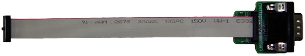
| Target cable | 14-pin type:Cable length: Approximately 42 cm |
| GND cable | Approximately 1 m |
| Compliance with overseas standards | European Standards: EN 55032 Class A, EN 55024 US FCC Standard: FCC part 15 Class A |
Notes:
- Connecting to the host PC has to use a cross cable.
- The maximum power-supply current is 100 mA when USB bus power is being supplied; however, this depends on the performance of the USB host in terms of the supply of power.
- The power adapter that comes with the PG-FP6 varies with the region where it is to be used. For the product type names, see Ordering Information.
Components
| PG-FP6 | GND cable | USB cable | Target cable (14-pin) | Power supply adapter |
Image  | Image  | Image  | Image  | Image  |
Notes:
- The regulations with which the PG-FP6 conforms and plug shape vary depending on regions where the order is made. See Power supply adapter. >>
- Conversion Adapters or Cables are provided as optional products. See optional products. >>
- Programming GUI, FP6 Terminal, is available here for download.
Ordering Information
| Region | Ordering Number |
|---|---|
| Japan | RTE0T00001FWRJP000R |
| Europe, USA | RTE0T00001FWREA000R |
| China, Hong Kong, Chinese Taipei, South Korea, Singapore | RTE0T00001FWRAS000R |
Notes:
- Since regulations that apply to the PG-FP6 vary with the region, we cannot ship a product to a region other than that from which the order was made. For example, if you place an order in Japan, you cannot purchase a product intended for Europe and the USA. Please purchase the product from a Renesas Electronics Corporation representative (responsible for sales) or distributor in the region where it is to be used.
- If you wish to know which model is available in a region not included in the above table, please contact either a Renesas Electronics Corporation representative (responsible for sales) or distributor.
- The power adapter that comes with the PG-FP6 complies with the regulations that are applicable in the target region. Its plug is also in the shape that is usable in that region.
Power Supply Adapter
The PG-FP6 includes a power supply adapter which conforms with the regulations and plug shapes in the region where the order is made.
| Region | Plug Shape | Voltage | |||
|---|---|---|---|---|---|
| Japan | Image A | AC: 100-240V Note1 | |||
| Europe | Image SE | Image C | Image BF | Image A | |
| USA | |||||
| China | |||||
| Hong Kong | |||||
| Chinese Taipei | |||||
| South Korea | |||||
| Singapore | |||||
Note:
- This is the range of voltages that the power-supply adapter can support. For the actual voltage through the power-supply cable, check the indication often be at the end of the casing for the plug.
PG-FP6 Usage Examples
Stand-alone (off-line) programming
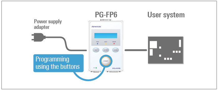
Field programming
Production line programming
PC programming
Optional Products
Following optional products are provided to facilitate the use of the PG-FP6.
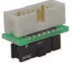
- Conversion Adapter
- 20-Pin Conversion Adapter for the PG-FP6 [RTE0T00001FWRB0000R]
- 14-Pin to 16-Pin Conversion Adapter for the E1 Emulator [QB-F14T16-01]
- Converter Cable
- User-system Interface Cable for the E2 Emulator (20-10 pins) [RTE0T00020KCAC1000J]
- Cable
- User-system Interface Cable for the E2 Emulator (20-20pins) [RTE0T00020KCAC0000J]
Conversion Adapter
20-Pin Conversion Adapter for the PG-FP6 [RTE0T00001FWRB0000R]
This adapter is used for converting the 15-pin D-sub connectorNote1 to be connectable to the 20-pin CoreSight connector. The adapter comes with a 20-pin CoreSight cable (approximately 150-mm long).
Purpose: Programming RA- or RE-family MCUs on boards which have 20-pin CoreSight connectors.
Note:
- The target connecter on the PG-FP6.
20-Pin Conversion Adapter for the PG-FP6
14-Pin to 16-Pin Conversion Adapter for the E1 Emulator [QB-F14T16-01]
This adapter converts the 14-pin, 2.54-mm pitch connector of the target cable to be connectable to the 16-pin, 2.54-mm pitch connector of the PG-FP5 or MINICUBE2.
Purpose: Programming 78K- or V850-family MCUs on boards which have 16-pin connectors.
Converter Cable
User-system Interface Cable for the E2 Emulator (20-10 pins) [RTE0T00020KCAC1000J]
RTE0T00020KCAC1000J User's Manual User-system Interface Cable for the Emulator(20-10 pins) (PDF | English, 日本語)
This cable is used for converting a CoreSight 20-pin connector to fit a CoreSight 10-pin connector, and is available for separate purchase. Use this conversion cable (approximately 150-mm long) along with the 20-pin conversion adapter for the PG-FP6.
Purpose: Programming RA- or RE-family MCUs on boards which have 10-pin CoreSight connectors.

Cable
User-system Interface Cable for the E2 Emulator (20-20pins) [RTE0T00020KCAC0000J]
RTE0T00020KCAC0000J User's Manual User-system Interface Cable for the Emulator (20-20 pins) (PDF | English, 日本語)
This 20-pin CoreSight cable (approximately 150-mm long) is available for separate purchase. This cable also comes with the 20-pin conversion adapter for the PG-FP6.
Purpose: For use when, for example, the cable that comes with the product is damaged.

Support
Support Communities
- PG-FP6
通电没有反应
Apr 7, 2025 - R8C microcontroller and PG-FP6 flashing device
... MCU is legacy. i have a R8C target board with MCU R5F21336C on it and want to flash my MOT file on this MCU with the PG-FP6 device. can you provide me with the correct wiring (connection) between the PG-FP6 14-pins target connector and this MCU. thanks
Nov 4, 2025 - pg-FP6 in Production
Hello, we have a group of products wich use allt he same kind of µC but different firmware. i want to build a flashing station with an PG-FP6. when i scann the Datamatix from the board i can detect which board is insde the flashstation, now i have to ...
Aug 12, 2021
Knowledge Base
- MCU Flash Erasure at Connection with Flash Programming Tool (PG-FP5/PG-FP6/RFP/FDT)
... tool you are using. Click here for the user’s manual of the Renesas Flash Programmer. Click here for the user’s manual of the PG-FP5 Click here for the user’s manual of the PG-FP6Click here for the user’s manual of the Flash Development Toolkit
Jun 11, 2021 - RH850: Programmer change from E1 to PG-FP6
... programming that is parts of the Data Flash which are not present in the hex file will not be written. The option for the RFP is the shown in the screen shot: For the PG-FP6 the default option is to write those data and this needs to be changed.
Jul 24, 2024 - Specifying erase/program operation depending on areas (PG-FP5/PG-FP6)
In PG-FP5/PG-FP6, it is not possible to switch between erase and program operations depending on areas in a single write.Instead, you can create a setting file for each operation, download the setting file to a PG-FP5/PG-FP6 programming area, and switch the ...
Jun 8, 2020

Support Communities


