
Overview
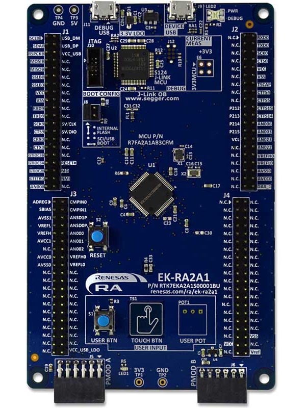
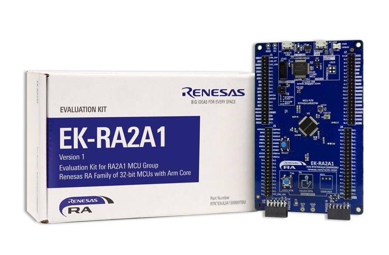
The EK-RA2A1 evaluation kit enables users to effortlessly evaluate the features of the RA2A1 MCU Group and develop embedded systems applications using Renesas' Flexible Software Package (FSP) and various IDEs.
Getting Started
Running the Quick Start Example Project
- The EK-RA2A1 board comes pre-programmed with a quick start example project (provided with the example projects bundle).
- Power up the EK-RA2A1 board through the USB debug port (J11) using the micro USB device cable connected to a 5V power source. The green power LED will light up.
- The quick start example project will begin to execute blinking the red user LED.
- Refer to the EK-RA2A1 Quick Start Guide to explore additional functionality of the quick start example project.
Developing Embedded Applications
- Modifying the quick start example project – refer to the EK-RA2A1 Quick Start Guide for instructions on importing, modifying and building the quick start example project.
- Start with one of the many other example projects (provided in the example projects bundle) – choose from many example projects to learn about different peripherals of the RA2A1 MCU group. These example projects can serve as excellent starting points for you to develop your custom applications.
Building Custom Hardware
- Start by building a functional prototype - utilize the EK-RA2A1 board with your choice of ecosystem add-ons.
- Build custom hardware – develop custom hardware by referring to the design and manufacturing information provided in the EK-RA2A1 v1 - Design Package (ZIP | English, 日本語)
Features
- MCU Native Pin Access:
- R7FA2A1AB3CFM MCU
- 48MHz, Arm Cortex®-M23 core
- 256kB Code Flash, 32kB SRAM
- 64-pin LQFP (10mm x 10mm x 1.7mm, 0.5mm pitch)
- Native pin access through 4x 40-pin male headers
- MCU current measurement points
- Ecosystem & System Control Access:
- USB Full Speed device
- 5V input through USB debug
- SEGGER J-LinkTM on-board programmer and debugger
- Debug modes
- Debug On-board (SWD) – via J-Link
- Debug Out (SWD) – via J-Link
- Debug in (SWD and JTAG)
- Two Digilent PmodTM (SPI and UART)
- User LED
- Mechanical user button
- Capacitive user button
- MCU boot configuration jumper
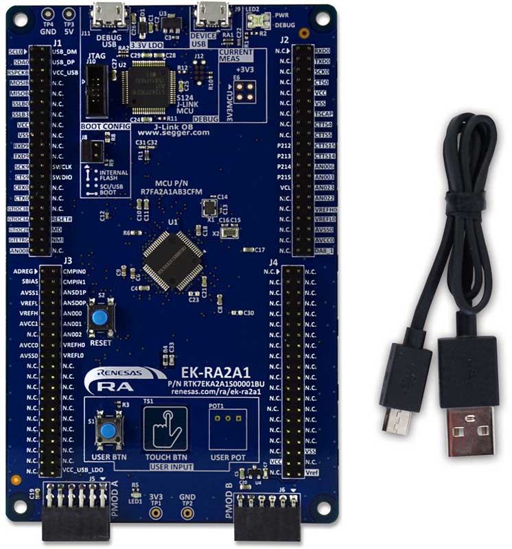
- Kit Contents: EK-RA2A1 v1 board, Micro USB device cable (type-A male to micro-B male)
Getting Started
Explore Ready-to-Run Solutions
Sample & Buy

Evaluation Kit for RA2A1 MCU Group
| Description: | Evaluation Kit for RA2A1 MCU Group |
| HTS (US): | 8471.50.0150 |
| ECCN (US): | 3A991.a.2 |
| SPQ: | 1 |
| Pb (Lead) Free: | No |
| Assembly Location: | CHINA |
| Easy to Start: | 1 |
Add-on Hardware

Evaluation Kit for RA2L1 MCU Group

Evaluation Kit for RA2E1 MCU Group

Evaluation Kit for RA2E2 MCU Group
Application Block Diagrams
 | Waste Collection Fleet Management System Smart waste management system boosts efficiency with weight tracking, route optimization, and real-time monitoring. |
Videos & Training
Kickstart IoT and embedded systems development using Renesas EK-RA2E1 and EK-RA2L1, Evaluation Kits for RA2E1 and RA2L1 MCU Groups. Familiarize yourself with the kit architecture, key features, quick start example project and many useful resources to begin innovating quickly.
Additional Videos
News & Blog Posts
Blog Post Jan 28, 2022 |
Blog Post Jan 28, 2022 |
Blog Post Nov 18, 2021 |
Blog Post Nov 11, 2021 |
Support
Support Communities
- EK-RA2A1 Sample Code- missing libraries
Hello, I have just started working with the EK-RA2A1 and I have downloaded the EK-RA2A1 Example Project Bundle - Sample Code, but when I import the projects, several warnings regarding not-found libraries are shown. Specifically, libraries that should be contained in subfolders of the projects folders, i.e ...
Mar 10, 2021 - EK-RA2A1 Not Working With Keil J-Link and Does Not Support
Error: Flash Download failed - "Cortex-M23" The program is not transferred to the EK-RA2A1 Development board with Keil J-Link. Does not support R7FA2A1AB3CFM processor. It supports R7FA2A1AB processor. I downloaded J-Link 7.64b version but still not supportedhttps://www.segger.com/downloads/supported ...
Apr 15, 2022 - SystemView J-Link recorder configuration issue on EK-RA2A1 (Cortex-M23, FreeRTOS v11 + e²studio)
Hello, I’m working with a Renesas EK-RA2A1 board (Cortex-M23 + J-Link OB) using e²studio and a FreeRTOS v11 blinky demo generated by the RA configurator (RA files are non-editable). I manually added all the SEGGER SystemView and RTT .c/.h files to the project, and ...
Dec 3, 2025
Knowledge Base
- RA Family: How to use the Debug Out function of J-Link OB on EK (Evaluation Kit)
Last Updated: 12/14/2023 Question: How to use the Debug Out function of J-Link OB on EK (Evaluation Kit) Answer: Renesas has equipped each EK (Evaluation Kit) for RA MCUs, such as EK-RA2E1, EK-RA2E2, EK-RA2L1, EK-RA2A1, etcEK-RA4M1、EK-RA4M2、EK-RA4M3 ...
Dec 14, 2023 - Buffering DAC8 Outputs with on-chip Op Amp on RA2A1 in FSP 3.0.0
The below attached project demonstrates the configuration and use of the RA2L1 Op Amp to buffer the output of the DAC08 using FSP 3.0.0 on the EK-RA2A1 kit.The program opens the DAC08 0 and DAC08 1 channels, opens the Op Amp and then starts the Op ...
Jun 10, 2021 - RA FSP Example Project Summaries: Analog
... is also displayed by the Segger RTT Viewer. ADC Modules Used: ADC and IOPORT This project initializes the ADC in single scan mode (on the EK-RA2A1 and EK-RA4M1 kits) or continuous scan mode (on other kits). The user can start and stop the ADC scan and view results ...

Support Communities

