Overview
Description
The EK-RA2A1 evaluation kit enables users to effortlessly evaluate the features of the RA2A1 MCU Group and develop embedded systems applications using Renesas' Flexible Software Package (FSP) and various IDEs.
Getting Started
Running the Quick Start Example Project
- The EK-RA2A1 board comes pre-programmed with a quick start example project (provided with the example projects bundle).
- Power up the EK-RA2A1 board through the USB debug port (J11) using the micro USB device cable connected to a 5V power source. The green power LED will light up.
- The quick start example project will begin to execute blinking the red user LED.
- Refer to the EK-RA2A1 Quick Start Guide to explore additional functionality of the quick start example project.
Developing Embedded Applications
- Modifying the quick start example project – refer to the EK-RA2A1 Quick Start Guide for instructions on importing, modifying and building the quick start example project.
- Start with one of the many other example projects (provided in the example projects bundle) – choose from many example projects to learn about different peripherals of the RA2A1 MCU group. These example projects can serve as excellent starting points for you to develop your custom applications.
Building Custom Hardware
- Start by building a functional prototype - utilize the EK-RA2A1 board with your choice of ecosystem add-ons.
- Build custom hardware – develop custom hardware by referring to the design and manufacturing information provided in the EK-RA2A1 v1 - Design Package (ZIP | English, 日本語)


Features
- MCU Native Pin Access:
- R7FA2A1AB3CFM MCU
- 48MHz, Arm Cortex®-M23 core
- 256kB Code Flash, 32kB SRAM
- 64-pin LQFP (10mm x 10mm x 1.7mm, 0.5mm pitch)
- Native pin access through 4x 40-pin male headers
- MCU current measurement points
- Ecosystem & System Control Access:
- USB Full Speed device
- 5V input through USB debug
- SEGGER J-LinkTM on-board programmer and debugger
- Debug modes
- Debug On-board (SWD) – via J-Link
- Debug Out (SWD) – via J-Link
- Debug in (SWD and JTAG)
- Two Digilent PmodTM (SPI and UART)
- User LED
- Mechanical user button
- Capacitive user button
- MCU boot configuration jumper
- Kit Contents: EK-RA2A1 v1 board, Micro USB device cable (type-A male to micro-B male)
Applications

|
Waste Collection Fleet Management System
Smart waste management system boosts efficiency with weight tracking, route optimization, and real-time monitoring.
|
Documentation
|
|
|
|
|---|---|---|
| Type | Title | Date |
| Quick Start Guide | PDF 801 KB | |
| Manual - Development Tools | PDF 3.31 MB 日本語 | |
| PCB Design Files | EK-RA2A1 v1 - Design Package
|
|
| Application Note |
PDF
704 KB
The EK-RA2A1 example project shows how to write code for various Renesas Flexible Software Package (FSP) modules supported by the EK-RA2A1 kit. The Flexible Software Package provides an optimized, easy-to-use, scalable, and high-quality software solution for embedded system design.
|
|
| Tool News - Release | PDF 533 KB 日本語 | |
| Release Note | PDF 1.34 MB 日本語 | |
| Tool News - Release | PDF 318 KB 日本語 | |
| Application Note |
PDF
1.49 MB
日本語
AI-generated Summary:
The control program operates on the RA2A1 microcontroller on the EK-RA2A1 evaluation board, enabling communication with the QE for AFE development tool. It supports configuring registers and acquiring data from multiple analog peripherals including 24-bit Sigma-Delta and 16-bit A/D converters, high-speed and low-power analog comparators, 12-bit and 8-bit D/A converters, and operational amplifiers. Communication interfaces include SCI UART and USB PCDC, with high-speed USB-UART adapters supporting continuous high-speed sampling. The document details connection methods, firmware files, project configurations, and operational conditions for continuous and one-shot measurements, providing comprehensive guidance for evaluation and development using the RA2A1 group.
|
|
| Release Note | PDF 1.45 MB 日本語 | |
| Flyer | PDF 534 KB 日本語 | |
| Flyer | PDF 412 KB | |
| Presentation | PDF 7.02 MB | |
| Tool News - Release | PDF 237 KB 日本語 | |
| Flyer | PDF 487 KB 日本語 | |
| Manual - Development Tools | PDF 364 KB 日本語 | |
| Report | PDF 187 KB 日本語 | |
|
16 items
|
||
Design & Development
Software & Tools
Software & Tools
| Software title
|
Software type
|
Company
|
|---|---|---|
| RA Flexible Software Package (FSP) FSP is an enhanced software package designed to provide easy-to-use, scalable, high-quality software for embedded system designs using Renesas RA Family of Arm Microcontrollers.
Note: FSP with e² studio Installer (Platform Installer) will install the e² studio tool, FSP packs, GCC toolchain, and Segger J-Link drivers required to use this software. No additional installations are required.
|
Software Package | Renesas |
| QE for AFE: Development Assistance Tool for Analog Front End This development assistance tool supports the development of embedded systems to perform high-precision sensing for microcontrollers with built-in analog front-end (AFE). [Plugin for Renesas IDE "e2 studio"] [Standalone Version] [Support MCU/MPU:RA, RX]
|
Solution Toolkit | Renesas |
| Renesas Flash Programmer (Programming GUI) Flash memory programming software [Support MCU/MPU and devices: RA, RE, RX, RL78, RH850, RISC-V MCU, Renesas Synergy, DA1453x, DA1459x, DA1469x, DA1470x, DA148xx, Power Management, Renesas USB Power Delivery Family, ICs for Motor Driver/Actuator Driver, V850, 78K0R, 78K0]
|
Programmer (Unit/SW) | Renesas |
| QuickConnect Platform QuickConnect platform enables fast prototyping by providing compatible hardware and software building blocks.
|
Software and Hardware Development Tools | Renesas |
4 items
|
||
Sample Code
Sample Code
Filters
|
||
|---|---|---|
| Type | Title | Date Date |
| Sample Code | EK-RA2A1 Example Project Bundle
[Software=RA FSP],[Board=EK-RA2A1]
ZIP
8.82 MB
IDE:
e2 studio/GCC/AC6, IAR, Keil MDK
The EK-RA2A1 example project shows how to write code for various Renesas Flexible Software Package (FSP) modules supported by the EK-RA2A1 kit. The Flexible Software Package provides an optimized, easy-to-use, scalable, and high-quality software solution for embedded system design.
|
|
| Sample Code | RA2A1 Group Board Control Program for 'QE for AFE' - Sample Code
[Software=RA Flexible Software Package|v5.6.0],[Toolchains=GNU Arm Embedded|13.2.1.arm-13-7]
ZIP
15.16 MB
日本語
Application:
Industrial
Compiler:
GNU ARM Embedded
Function:
Analog, Application Example, Communication Interface
IDE:
e2 studio
|
|
2 items
|
||
Related Boards & Kits
Boards & Kits
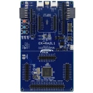
Evaluation Kit for RA2L1 MCU Group
The EK-RA2L1 evaluation kit enables users to effortlessly evaluate the features of the RA2L1 MCU Group and develop embedded systems applications using Renesas' Flexible Software Package (FSP) and e2 studio IDE. Utilize rich on-board features along with your choice of popular ecosystem add-ons to... Read More
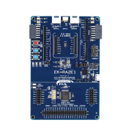
Evaluation Kit for RA2E1 MCU Group
The EK-RA2E1 evaluation kit enables users to effortlessly evaluate the features of the RA2E1 MCU Group and develop embedded systems applications using Renesas' Flexible Software Package (FSP) and e2studio IDE. Utilize rich on-board features along with your choice of popular ecosystem add-ons to... Read More
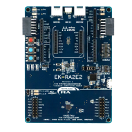
Evaluation Kit for RA2E2 MCU Group
The EK-RA2E2 evaluation kit enables users to effortlessly evaluate the features of the RA2E2 MCU Group and develop embedded systems applications using Renesas' Flexible Software Package (FSP) and e2 studio IDE. Utilize rich on-board features along with your choice of popular ecosystem add-ons to... Read More
Product Options
| Part Number | Status | Stock | Budgetary Price (USD) | Sampleable |
|---|---|---|---|---|
| RTK7EKA2A1S00001BU | Active | In Stock | 1u | $37.65 | Available |
Videos & Training
Kickstart IoT and embedded systems development using Renesas EK-RA2E1 and EK-RA2L1, Evaluation Kits for RA2E1 and RA2L1 MCU Groups. Familiarize yourself with the kit architecture, key features, quick start example project and many useful resources to begin innovating quickly.
Additional Videos
News & Blog Posts
Blog Post Jan 28, 2022 |
Blog Post Jan 28, 2022 |
Blog Post Nov 18, 2021 |
Blog Post Nov 11, 2021 |
Certifications
The EK-RA2A1 kit meets the following certifications/standards. Refer to the EK-RA2A1 user manual for the disclaimer, precautions and more details on the certifications.
EMC/EMI Standards
- FCC Notice (Class A) – Part 15
- Innovation, Science and Economic Development Canada ICES-003 Compliance: CAN ICES-3 (A)/NMB-3(A)
- CE Class A (EMC Directive 2004/108/EEC)
- Taiwan Chinese National Standard 13438, C6357 compliance, Class A limits
- Australia/New Zealand AS/NZS CISPR 32:2015, Class A
Material Selection, Waste, Recycling, and Disposal Standards
- EU RoHS
- China SJ/T 113642014, 10-year environmental protection use period
Safety Standards
- UL 94V-0
Partners
Zephyr Project
The Zephyr Project is an open-source, scalable real‑time operating system (RTOS) designed for resource-constrained embedded systems and supports a wide range of hardware architectures and development boards. For the Renesas RA2A1 Evaluation Kit, Zephyr provides focused documentation covering board features, supported peripherals, and basic build, flashing, and debugging workflows to help developers quickly get started.
Support
Support Communities
- EK-RA2A1 keil flash erase fail
Hi,I started developing for the R7A2A1AB3CFM Renesas mcu using the EK-RA2A1 board.The board comes equipped with a J-link debugger.I'm still trying to run a simple blinky example.The board hardware is ok because I can program and debug the board using e2studio, but I ...
Apr 21, 2022 - EK-RA2A1 CAN example
Hi, Can anybody share an example code for CAN with EK-RA2A1 kit This thread was automatically locked due to age.
Nov 27, 2020 - EK-RA2A1 Sample Code- missing libraries
Hello, I have just started working with the EK-RA2A1 and I have downloaded the EK-RA2A1 Example Project Bundle - Sample Code, but when I import the projects, several warnings regarding not-found libraries are shown. Specifically, libraries that should be contained in subfolders of the projects folders, i.e ...
Mar 10, 2021
Knowledge Base
- Connecting Reference Voltages for Proper ADC Operation on the EK-RA2A1
Last Updated:04/01/2021 On the EK-RA2A1 kit you need to connect the reference voltages for the ADC for correct operation. You can connect VREFL0 to AVSS0 or the readings you get will tend to be a raw value between about 32767 to 60000, which is ...
Apr 1, 2021 - RA Family: How to use the Debug Out function of J-Link OB on EK (Evaluation Kit)
Last Updated: 12/14/2023 Question: How to use the Debug Out function of J-Link OB on EK (Evaluation Kit) Answer: Renesas has equipped each EK (Evaluation Kit) for RA MCUs, such as EK-RA2E1, EK-RA2E2, EK-RA2L1, EK-RA2A1, etcEK-RA4M1、EK-RA4M2、EK-RA4M3 ...
Dec 14, 2023 - Buffering DAC8 Outputs with on-chip Op Amp on RA2A1 in FSP 3.0.0
The below attached project demonstrates the configuration and use of the RA2L1 Op Amp to buffer the output of the DAC08 using FSP 3.0.0 on the EK-RA2A1 kit.The program opens the DAC08 0 and DAC08 1 channels, opens the Op Amp and then starts the Op ...
Jun 10, 2021

Support Communities


