Overview
Description
Renesas Motor Workbench (RMW) is a development support tool for debugging, analyzing, and tuning motor control programs. It operates a motor control program from a PC or acquires the data in the program to strongly support motor control development.
For Renesas Motor Workbench users (how to renew your license)
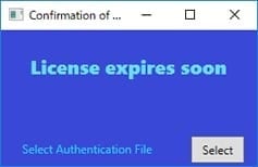
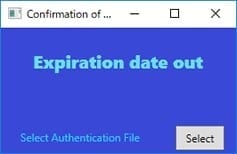
When starting this tool, the following messages regarding the license expiration date may be displayed.
License expire soon: The license will expire in less than 30 days.
Expiration date out: The license has expired.
The authentication function has been removed from V3.2.0. Please download and use the latest version of Renesas Motor Workbench.
Features
Renesas Motor Workbench is a development support tool for debugging, analyzing, and tuning motor control programs. Features include:
- Easy GUI
- Intuitive operation makes it easy to control motor speed and position.
- Analyzer
- Dynamic reading/writing of variables and waveform display while operating the motor.
- Tuner
- Automatic identification of motor parameters and control gains required for vector control. It's easy to fine-tune and the results are instantly visible.
- Servo
- Implements an adjustment function for the motor’s embedded position control system. (Supports adjustment of position control parameters, inertia estimation, origin return operation, and point-to-point control.)
- DLL
- Functions needed for debugging are provided as APIs, allowing connection to a GUI developed to the user’s specifications.
- Built-in communication library
- In addition to the standard library, a communication library for simple debugging using a commercially available serial-USB conversion cable or the like is provided.
- Learn more
Release Information
| Product Name | Latest Ver. | Released | Target Device | Details of upgrade | Download | Operating Environment |
|---|---|---|---|---|---|---|
| Renesas Motor Workbench | V3.3.1 | 2026/3/31 | RA Family RL78 Family RX Family | See Release Notes | Download | Windows 10 Windows 11 |
Latest Version: Motor Control Development Support Tool Renesas Motor Workbench 3.3.1 (ZIP)
- V3.3.1
- Added the communication port for RA8T2.
- Support for RX14T.
- V3.3.0
- Added log display function
- Changed the display content of the Tuner function
- V3.2.1
- Support for RA8T2.
- Support for RA2T1.
- Support for CPU board of RA6T2 Ver.2.
- V3.2.0
- Added Tuner function for RL78
- Added Tuner function for MCI-HV-1
- Added Windows 11 to system requirements
- Deletion of Authentication Function
- V3.1.2
- Support for RA8T1.
- V3.1.1
- Decimal point display and input is fixed to the period, regardless of the OS language setting.
- V3.1
- Added a function that allows you to output parameters adjusted by Analyzer to a header file.
- A Navigation function for GUI support has been added to explain the operating procedure of each function.
- Added functions for displaying variable uses.
- Added GUI for Servo control to perform inertia estimation, control parameter adjustment, return to origin, and PTP testing.
Target Devices
Note: RL78/G24 only has Analyzer and Tuner functionality. Other RL78 Family only has Analyzer functionality.
Downloads
|
|
|
|
|---|---|---|
| Type | Title | Date |
| Software & Tools - Other | Motor Control Development Support Tool Renesas Motor Workbench 3.3.1
|
|
| Software & Tools - Other | Renesas Motor Workbench DLL for communication
|
|
2 items
|
||
Documentation
|
|
|
|
|---|---|---|
| Type | Title | Date |
| Quick Start Guide |
PDF
3.92 MB
日本語
Describes procedures for the Renesas Motor Workbench, from installation to execution.
|
|
| Manual - Development Tools |
PDF
20.29 MB
日本語
Describes the various functions and operating procedures of the motor control development support tool, Renesas Motor Workbench.
|
|
| Release Note |
PDF
165 KB
日本語
Covers Renesas Motor Workbench 3.3.1 installation, restrictions, and so on.
|
|
| Release Note |
PDF
166 KB
日本語
Explains how to install Renesas Motor Workbench 3.3.0, restrictions, and so on.
|
|
| Release Note |
PDF
170 KB
日本語
Describes how to install Renesas Motor Workbench 3.2.1, restrictions, and so on.
|
|
| Release Note | PDF 178 KB 日本語 | |
| Release Note | PDF 161 KB 日本語 | |
| Application Note |
PDF
1.57 MB
日本語
AI-generated Summary:
The document details the use of a DLL that facilitates communication between user-created software (such as C# or Excel VBA) and motor control microcomputers via USB. It covers functions including connecting/disconnecting, reading and writing global variables, continuous data reading, and motor parameter measurement and adjustment. The DLL operates within a Windows 10 environment with .NET Framework 4.6.1 or higher and supports Visual Studio 2015 and Excel. The system configuration involves a PC running user software, the DLL, a communication board, and the microcomputer controlling the motor.
|
|
8 items
|
||
Design & Development
Related Boards & Kits

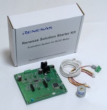
Evaluation System for BLDC Motor
The Evaluation System for BLDC Motor provided by Renesas is a low-voltage permanent magnet synchronous motor (brushless DC motor) solution that allows anyone to easily evaluate the motor. After purchase, you can download the software from the website and start evaluating immediately.
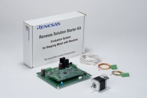
Evaluation System for Stepping Motor with Resolver
This solution kit allows you to easily evaluate and study the RX family and resolver to digital converter (RDC) ICs provided by Renesas. A stepping motor with resolver is included, and evaluation can be started immediately after purchasing the kit using software that can be downloaded from the... Read More
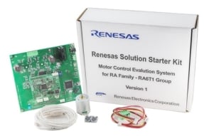
Renesas Flexible Motor Control Kit for RA8T1 MCU Group
The MCK-RA8T1 is a development kit that enables easy evaluation of motor control using permanent magnet synchronous motors (brushless DC motors). With this product and the sample code and QE for Motor that can be downloaded from the website, you can start evaluating motor control using the RA8T1... Read More
Motor Control Evaluation System for RA Family - RA6T1 Group
The Motor Control Evaluation System for RA Family - RA6T1 Group is a low-voltage permanent magnet synchronous motor (brushless DC motor) solution that allows anyone to easily evaluate motor control. Start evaluating motor control immediately using the kit hardware and software available for... Read More

Renesas Flexible Motor Control Kit for RA6T2 MCU Group
The MCK-RA6T2 is a development kit that enables easy evaluation of motor control using permanent magnet synchronous motors (brushless DC motors). With this product and the sample code and QE for Motor that can be downloaded from the website, you can start evaluating motor control using the RA6T2... Read More

Renesas Flexible Motor Control Kit for RA6T3 MCU Group
The MCK-RA6T3 is a development kit that enables easy evaluation of motor control using permanent magnet synchronous motors (brushless DC motors).
With this product and the sample code and QE for Motor that can be downloaded from the website, you can start evaluating motor control using the RA6T3... Read More

Renesas Flexible Motor Control Kit for RA4T1 MCU Group
The MCK-RA4T1 is a development kit that enables easy evaluation of motor control using permanent magnet synchronous motors (brushless DC motors).
With this product and the sample code and QE for Motor that can be downloaded from the website, you can start evaluating motor control using the RA4T1... Read More
Renesas Flexible Motor Control Kit for RX26T MCU Group
The MCK-RX26T is a development kit that enables easy evaluation of motor control using permanent magnet synchronous motors (brushless DC motors). With this product and the sample code and QE for Motor that can be downloaded from the website, you can start evaluating motor control using the RX26T... Read More

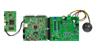
Renesas Flexible Motor Control Communication Board

Renesas Flexible Motor Control Kit for RA8T2 MCU Group
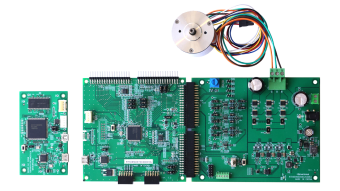
The MCK-RA8T2 is a development kit designed for easy evaluation of motor control using permanent magnet synchronous motors (brushless DC motors). This kit includes the RA8T2 CPU board (MCB-RA8T2), an inverter board (MCI-LV-1), a permanent magnet synchronous motor, and accessories such as cables... Read More
Renesas Flexible Motor Control Kit for RA2T1 MCU Group
The MCK-RA2T1 is a development kit that enables easy evaluation of motor control using permanent magnet synchronous motors (brushless DC motors). With this product and the sample code and QE for Motor that can be downloaded from the website, you can start evaluating motor control using the RA2T1... Read More
Videos & Training
- PC software installation
- PC to board connection
Additional Details
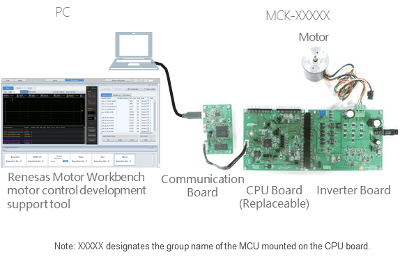
Renesas Motor Workbench provides powerful support for developers of motor control applications, allowing operation of motor control programs from a PC and extraction of data within programs.
Example setup
Renesas Motor Workbench Functions
- Easy GUI
- Makes it quick and easy for anyone to implement motor speed and position control by means of intuitive operations.
- Analyzer
- Dynamic reading/writing of variables and waveform display while operating the motor.
- Tuner
- Automatic identification of motor parameters and control gains required for vector control.
- Servo
- Implements an adjustment function for the motor’s embedded position control system. (Supports adjustment of position control parameters, inertia estimation, origin return operation, and point-to-point control.)
- DLL
- Functions needed for debugging are provided as APIs, allowing connection to a GUI developed to the user’s specifications.
Function Details
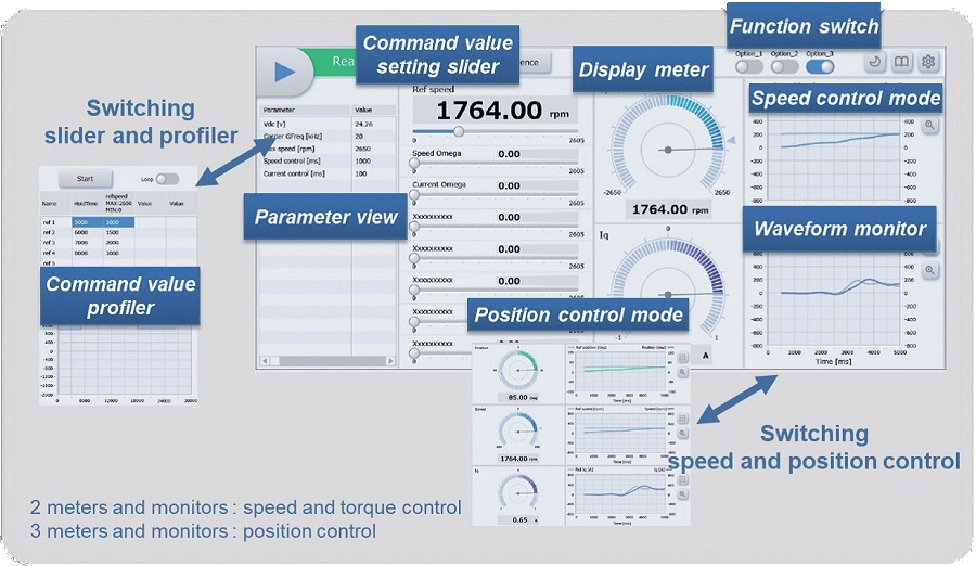
Easy GUI
Implements a GUI that allows more intuitive operation of the motor.
- Ability to set instruction values by manipulating sliders.
- Ability to configure instruction value profiles.
- Display of rotation speed, current values, etc., on meters.
- Switches for function switching.
- Waveform display of changes in values of variables.
- Ability to display a variety of parameters.
Analyzer
Read and write variables dynamically while driving a motor.
- Dynamically display waveform while driving a motor.
- Specify trigger and each display settings with the waveform display.
- The commander function allows creation and transmission of sequences for changing variables of your choice.
- The user button function lets you change a user-defined group of variables with a single click.
- Operating procedure of each RMW function is displayed while you work.
- Adjusted variables can be output as macro definitions to header files.
- Display variable usage information by reading a CSV file.

Tuner
- Automatically measures motor-specific parameters (resistance, inductance, induced voltage constant, inertia).
- Automatically adjust the proportional integral (PI) control gain of current/speed/position.
- Automatically adjust the expected gain for sensorless vector control.
- Manual tuning to finely adjust each PI control.
- Output results in pdf and motor-driver header files.
- [New in RMW 3.2] Added Tuner function for MCI-HV-1.

Tuner for RL78 [New in RMW 3.2]
- Automatically measure motor-specific parameters (resistance, inductance, BEMF constant, inertia, friction coefficient, parameters for initial position detection).
- Automatically design parameters for sensorless vector control and fixed point arithmetic.
- Manually adjust each parameter.
- Easily perform drive tests such as startup, steady-state drive, and step response of speed and current.
- Output results in pdf and motor-driver header files.

Servo
The following GUI for Servo control has been implemented. The Servo Adjustment screen is displayed when you select [Servo] from Select Tool in the Main Window.
- Motor axis connected load inertia estimation function
- Servo setting configuration function covering position control type, fixed frequencies, etc.
- Function for configuring the origin return method, return speed, etc.
- Function for point-to-point (PTP) single-axis operation.

DLL
Variable read and write functions executed by the RMW (GUI) are provided in a DLL, making it possible to create tools using Excel VBA or as .NET applications.

Built-in Communication Library
The download package contains both a standard communication library and a built-in communication library. Embedding the built-in communication library in the motor control program allows you to perform simple debugging using a USB-serial conversion board instead of a communication board compatible with Renesas Motor Workbench. Supported MCUs are the RA8T1, RA8T2, RA6T2, RA6T3, and RA4T1 (with support for additional MCUs planned for future release).
The number of points of waveform display data that can be displayed using the Analyzer module is limited, but other functions can be used in the same way as when using a communication board.

| Standard Library | Built-in Communication Library | ||
|---|---|---|---|
| RMW | Maximum display channels | 12 | 8 |
| Number of waveform display data points | 100000 | 1000 (RA8T1, RA8T2, RA6T2) 500 (RA6T3, RA4T1) | |
| Sampling period | Max. 20µs/4ch *UART 16.6Mbps | 50µs/8ch | |
| Commander | Available | Available | |
| User Button | Available | Available | |
| Tuner | Available | Available | |
| Easy GUI | Available | Available | |
| Connection to PC | MC-COM communication board required | Works with commercially available USB/UART conversion boards | |
| MCU communication interface | UART: 1 channel | UART: 1 channel | |
| Buffer | Uses external RAM built into the communication board | Uses MCU's internal RAM (32KB) | |
Detailed Specifications
| Item | Specifications | |
|---|---|---|
| General | Supported MCUs | RX13T, RX14T, RX23T, RX24T, RX24U, RX26T, RX66T, RX72T, RX72M, RA2T1, RA6T1, RA6T2, RA6T3, RA4T1, RA8T1, RA8T2, RL78/G1F, RL78/G14, RL78/G24 (RL78/G24 only has Analyzer and Tuner functionality. Other RL78 Family only has Analyzer functionality.) |
| Usage environment (OS) | Windows 10, Windows 11 | |
| Communications | Peripherals & ports | UART 1 ch, DMA (DTC) Port: TXD, RXD |
| Communication interface | USB 2.0 (Communication Device Class) | |
| Communication board | The following kits have communication circuits:
For MCK-XXXXX or user board:
| |
| Analyzer | Waveform display | 8ch (scale and off-set setting per channel), zoom function (2 windows), Trigger mode selectable from Single / Auto / Normal, waveform data in a CSV format |
| Write / Read variable | Ability to select up to 255 variables simultaneously, useful functions that simplify debugging (user buttons, commander function, rename function) | |
| Number of waveform display data points | 100,000 (using standard library) | |
| Tuner | Input information | Rated voltage and number of pole pairs of motor to be measured |
| Output information | Motor-unique parameter (Resistance, Inductance, Magnet flux, Rotor inertia) and Control gain output Output file format: pdf file, header file*1 | |
| Servo | Supported functions | Inertia estimation function (rotor + load), servo adjustment function, origin return processing, PTP control |
| DLL | Usage environment | Windows 10 only. .NET Framework 4.6.1 or later. |
| Development environment | Visual Studio 2015 or later, Excel | |
| Supported functions | Serial data connection, reading and writing variables, scope function | |
| Built-in communication library | Supported MCUs | RA8T1, RA8T2, RA6T2, RA6T3, RA4T1 |
| Communication board | Commercially available USB serial conversion cable or board | |
| Number of analyzer waveform display data points | RA8T1/RA8T2/RA6T2: 1,000 data points RA6T3/RA4T1: 500 data points | |
*1. Corresponds to sample files for motor control sample code released by Renesas. Refer to the user’s manual for Renesas Motor Workbench for details.
Usage Environment
- MCK-XXXXX (RA4T1/RA6T2/RA6T3/RA8T1/RA8T2/RA2T1/RX26T/RX14T)
- Evaluation System for BLDC Motor (requires CPU board sold separately)
- Evaluation System for Stepping Motor with Resolver
- User's development board (need to prepare a separate communication board)
Communication boards
- Renesas Electronics MC-COM
- Desk Top Laboratories W2002 (http://www.desktoplab.co.jp/)
- Commercially available USB-to-serial conversion cable (when using the built-in communication library)
Example setups
Evaluation System for BLDC Motor / for Stepping Motor with Resolver

MCK-XXXXX

User environment

Resources
Support
Support Communities
- Renesas Motor Workbench - Licensing
HI Could you please let me know that the license type of RMW tool. Form the official page it is seen that. But not found any information related to license type. So please let me know the license type ASP. This thread was automatically locked due to age.
Jan 7, 2026 - Precise parameters available in Renesas Motor Workbench
Bonjour à tous, I would like to use Renesas Motor Workbench but I don't understand all the parameters that can be manipulated. I use the program RA6T2_MCILV1_SPM_LESS_120_E2S_V110 and here is the list of parameters: Does anyone know where to find clarification on this ...
Jun 8, 2023 - Old Version of Renesas Motor Workbench
Hello everyone, I'm writing to this group because I've been redirected here for Renesas Motor Workbench problems. Does anyone have a version prior to v3.1 or know where I can find it? Thanks in advance. Best, Grégoire
Jun 7, 2023

Support Communities


