
Overview
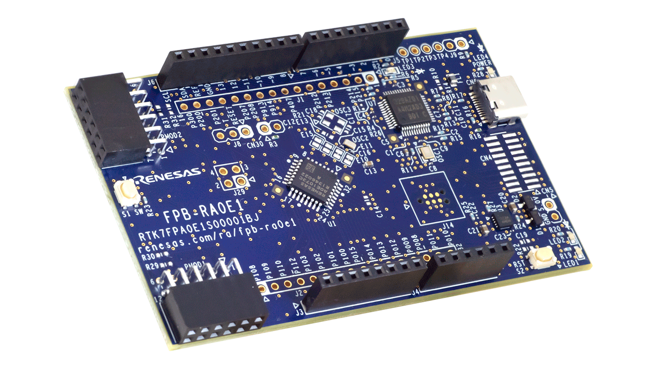
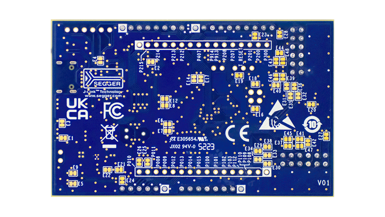
The RA0E1 Fast Prototyping Board is equipped with an RA0E1 MCU, making it an evaluation board specialized for prototype development for a variety of applications. It has a built-in SEGGER J-Link™ emulator circuit so you can write and debug programs without additional tools. In addition, it includes Arduino® UNO and Pmod™ interfaces as standard, along with through-hole access to all pins of the microcontroller, offering high expandability.
Sample software is available to demonstrate the functionality of the RA0E1 MCU and to facilitate connections between the RA0E1 Fast Prototyping Board and various wireless or sensor modules. The kit includes the FPB‑RA0E1 v1 board and either a USB 2.0 Type‑C™ cable (Type‑A male to Type‑C male) or a USB 2.0 Type‑C cable (Type‑C male to Type‑C male); the cable type varies by FPB lot number.
Features
- Equipped with an RA0E1 32-bit microcontroller (R7FA0E1073CFJ):
- 32MHz, Arm® Cortex®-M23 Core
- 64KB ROM, 12KB RAM, Data Flash: 1KB
- 32-pin LQFP (7mm x 7mm x 1.7mm, 0.8mm pitch)
- No additional tools are required for program writing/debugging with the built-in SEGGER J-Link™ emulator circuit
- Through-holes with access to all of the pins of the MCU
- Arduino UNO and Pmod interfaces
- Small size board: 53mm x 85mm
- Support for various RA0E1 software and tools

Sample & Buy
Fast Prototyping Board for the RA0E1 MCU Group
| Description: | Fast Prototyping Board for the RA0E1 MCU Group |
| SPQ: | 1 |
| Pb (Lead) Free: | No |
| Assembly Location: | CHINA |
Videos & Training
This video demonstrates the RA0E1 fast prototyping board, designed for the RA0E1 MCU. It includes a built-in SEGGER J-Link emulator circuit, enabling program writing and debugging without additional tools. The board also provides Arduino UNO and Pmod™ interfaces, along with through-hole access to all microcontroller pins for enhanced expandability.
Additional Videos
News & Blog Posts
Blog Post Apr 22, 2025 |
Blog Post Apr 9, 2024 |
Support
Support Communities
- Systick code for FPB-RA0E1
Hi As a part of some of my project i want to use SysTick timer. Following are my working environment IDE : e2studio. FSP : 5.6.0 EVK : FPB-RA0E1 I am not fully familiarized the peripherals of FPB-RA0E1 and also i am not so-much familiar with e2studio environment ...
Feb 10, 2025 - FPB-RA0E1 datasheet
Hi, i could not fount the FPB-RA0E1 data sheet with register level details of each modules. i only got one with respect to RA0E1 grp datasheet with 73 pages only (link for that - https://www.renesas.com/en/document/dst/ra0e1-group-datasheet ...
Nov 25, 2024 - reception event is not generate for I2C communication, FPB-RA0E1 and external EEPROM communication
Hi, i wanted to communicate I2C master as FPB-RA0E1 and external EEPROM as slave device. The steps i flow is given below. - Create new bare metal project for R7FA0E1073CFJ as shown below - Create SAU_I2C module in stack tab and configure the properties. Slave address is 0x50 - Create my ...
Nov 21, 2024
Knowledge Base
- How to Use Real-Time Clock on FPB-RA0E1
Last updated on 1st June 2026 Summary of the video This video demonstrates how to update and read the RTC on RA0E1 Fast Prototyping Board using UART input. Flexible Software Package (FSP) supports RTC operation with the r_rtc_c FSP module and serial communication with the r_uarta FSP ...
- How to Use Serial Peripheral Interface (SPI) Communication on RA0E1 Fast Prototyping Board
Last updated on 1st June 2026 Summary of the video This video demonstrates SPI communication between two Renesas RA boards, using the FPB-RA0E1 as the SPI master and the EK-RA6M5 as the SPI slave. FSP supports SPI communication on the FPB-RA0E1 with the r_sau_spi FSP ...
- RA and FSP Curriculum: I-002A Fundamentals of FSP (Non-Trustzone)
... are available in a single zip file located here. I-002A Fundamentals of FSP Presentation and Lab (Non-TrustZone) for FSP 5.4.0 with FPB-RA0E1- a step-by-step PPT hands-on lab using FSP 5.4.0 and the FPB-RA0E1 kit. It introduces FSP including components ...
May 19, 2026

Support Communities

