Design Considerations for Cost Reduction
Designers are continually seeking ways to reduce system costs while maintaining or enhancing functionality. At the same time, market demands for expanded features and shorter product cycles create additional challenges. Balancing these conflicting requirements requires innovative approaches to system design.
One effective strategy for cost reduction is simplifying the system architecture by reducing the number of components and using more cost-efficient ICs. However, any changes must ensure that system functionality remains the same—or ideally, improves.
Challenges in Reducing System Costs
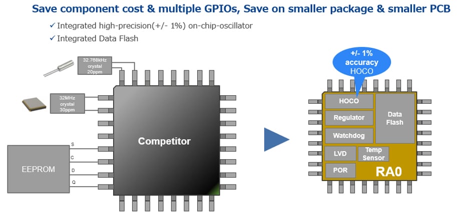
One approach to minimizing costs is eliminating external components, such as replacing an external oscillator with an on-chip oscillator or substituting external EEPROM with embedded Data Flash. This can lead to reduced system costs by decreasing both component count and board size. Additionally, it frees up extra pins, which can then be reassigned to other functions.
However, these optimizations present technical challenges. For instance, UART communication typically requires a clock frequency error within 2% to 3% to ensure reliable data transmission. If one communication device has a frequency error of 2%, the MCU must maintain an error margin of 1% or less to stay within the 3% total limit. Many low-end MCUs lack such high-precision oscillators, and even when specifications are provided in datasheets, they may require external resistors for tuning. Similarly, low-end MCUs with embedded EEPROM-like memory are not widely available.
RA0E2 MCU Benefits
The RA0E2 MCU addresses these challenges effectively. It features an on-chip high-speed oscillator with a maximum error of ±1%, guaranteed across all operating temperatures (-40 °C to 125 °C). Additionally, it integrates Data Flash, eliminating the need for external EEPROM. These features allow for a reduced component count, leading to lower system costs and simplified designs. Moreover, the freed-up pins can be utilized for GPIO or other functions, providing greater flexibility within the same package size.
Fast Prototyping
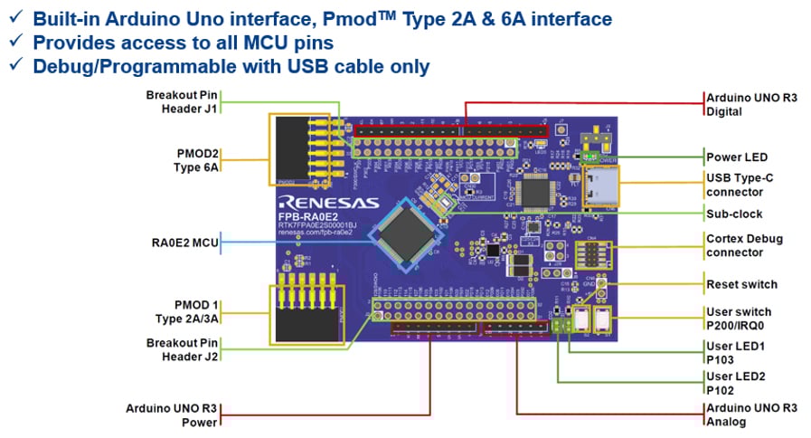
To accelerate RA0E2 MCU development, a Fast Prototyping Board (FPB) is available. This evaluation board is designed to streamline the evaluation process, enabling designers to develop and test prototype products more efficiently.
Summary
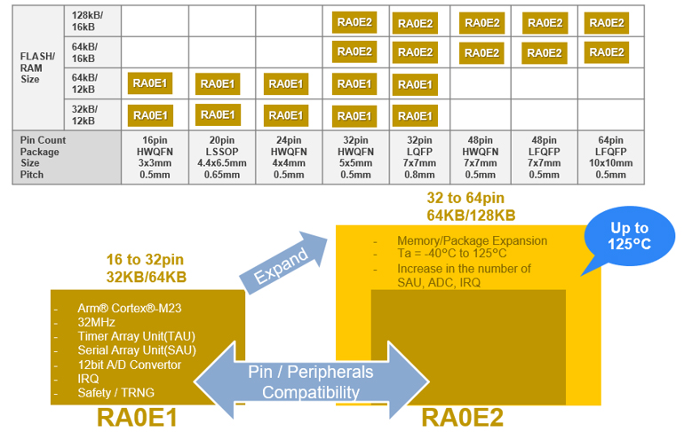
The RA0E2 MCU series offers valuable features that help designers achieve cost reduction without sacrificing performance. Together with the previously released RA0E1 MCU, the RA0 series provides a range of ROM sizes (32kB to 128kB) and pin-count options (16 to 64 pins), making it suitable for diverse applications. Additionally, the FPB-RA0E2 evaluation board offers an affordable solution for rapid prototyping, further simplifying the development process.
For more details on RA0E1 and RA0E2 features and benefits, please visit renesas.com/ra0e1 and renesas.com/ra0e2.
For more information about evaluation boards, please visit renesas.com/fpb-ra0e2.