

| CADモデル: | View CAD Model |
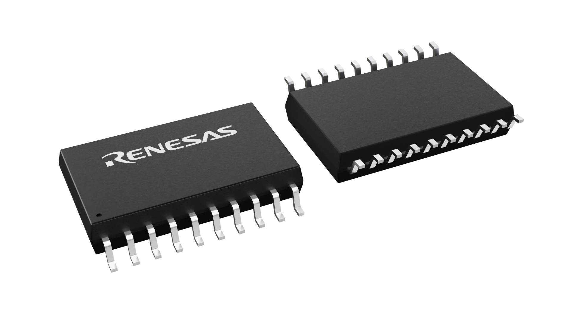
| Pkg. Type: | SOIC |
| Pkg. Code: | PSG20 |
| Lead Count (#): | 20 |
| Pkg. Dimensions (mm): | 12.8 x 7.6 x 2.34 |
| Pitch (mm): | 1.27 |
| Moisture Sensitivity Level (MSL) | 1 |
| Pb (Lead) Free | Yes |
| ECCN (US) | EAR99 |
| HTS (US) | 8542.39.0090 |
| Lead Count (#) | 20 |
| Carrier Type | Reel |
| Moisture Sensitivity Level (MSL) | 1 |
| Qty. per Reel (#) | 1000 |
| Qty. per Carrier (#) | 0 |
| Pb (Lead) Free | Yes |
| Pb Free Category | e3 Sn |
| Temp. Range (°C) | 0 to 70°C |
| C-C Jitter Max P-P (ps) | 50 |
| Core Voltage (V) | 3.3 |
| Divider Value | 1, 2, 4, 8 |
| Feedback Divider | 1 - 1, 2 - 2, 4 - 4, 8 - 8 |
| Input Freq (MHz) | 31.25 - 630 |
| Input Type | LVPECL, LVDS, HSTL, HCSL, SSTL |
| Inputs (#) | 1 |
| Length (mm) | 12.8 |
| MOQ | 1000 |
| Output Banks (#) | 1 |
| Output Freq Range (MHz) | 31.25 - 630 |
| Output Signaling | HSTL |
| Output Skew (ps) | 50 |
| Output Type | HSTL |
| Output Voltage (V) | 1.8 |
| Outputs (#) | 2 |
| Package Area (mm²) | 97.3 |
| Pitch (mm) | 1.27 |
| Pkg. Dimensions (mm) | 12.8 x 7.6 x 2.34 |
| Pkg. Type | SOIC |
| Product Category | Zero Delay Buffers |
| Reel Size (in) | 13 |
| Requires Terms and Conditions | Does not require acceptance of Terms and Conditions |
| Tape & Reel | Yes |
| Thickness (mm) | 2.34 |
| VCO Max Freq (MHz) | 630 |
| VCO Min Freq (MHz) | 250 |
| Width (mm) | 7.6 |
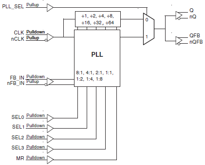
The 8725B-21 is a highly versatile 1:1 differential-to-HSTL clock generator. The CLK, nCLK pair can accept most standard differential input levels. The 8725B-21 has a fully integrated PLL and can be configured as zero delay buffer, multiplier, or divider, and has an output frequency range of 31.25MHz to 630MHz. The reference divider, feedback divider, and output divider are each programmable, thereby allowing for the following output-to-input frequency ratios: 8:1, 4:1, 2:1, 1:1, 1:2, 1:4, 1:8. The external feedback allows the device to achieve “zero delay” between the input clock and the output clocks. The PLL_SEL pin can be used to bypass the PLL for system test and debug purposes. In bypass mode, the reference clock is routed around the PLL and into the internal output dividers.