Package Information
| Pkg. Type: | TSSOP |
| Pkg. Code: | MPK |
| Lead Count (#): | 14 |
| Pkg. Dimensions (mm): | 5.00 x 4.39 x 0.00 |
| Pitch (mm): | 0.65 |
Environmental & Export Classifications
| Moisture Sensitivity Level (MSL) | 1 |
| Pb (Lead) Free | No |
| ECCN (US) | EAR99 |
| HTS (US) | 8542.39.0090 |
Product Attributes
| Lead Count (#) | 14 |
| Carrier Type | Reel |
| Moisture Sensitivity Level (MSL) | 1 |
| Pb (Lead) Free | No |
| Pb Free Category | Solder Plate |
| MOQ | 2000 |
| Temp. Range (°C) | -55 to +125°C |
| Channels (#) | 2 |
| Die Sale Availability? | No |
| End-to-End Temperature Coefficient (ppm/°C) | 50 |
| Flow | Harsh Environment & MIL-STD-883 |
| Interface | I2C |
| Length (mm) | 5.0 |
| Memory Type | Nonvolatile |
| Operating Freq Range (°C) | 125 |
| PROTO Availability? | No |
| Pitch (mm) | 0.7 |
| Pkg. Dimensions (mm) | 5.0 x 4.4 x 0.00 |
| Pkg. Type | TSSOP |
| Qualification Level | Standard |
| Rating | Harsh Environment |
| Resistance Options (kΩ) | 10 |
| Resistance Taper | Linear |
| Single Supply Voltage Range (V) | 0 - 5.5 |
| Supply Current Icc (µA) | 5 |
| Supply Voltage (max) (V) | 5.5 - 5.5 |
| Supply Voltage (min) (V) | 2.7 - 2.7 |
| Supply Voltage Vcc (Min) (V) | 2.7 |
| Supply Voltage Vcc Range | 2.7-5.5 |
| Taps (#) | 128 |
| Thickness (mm) | 0.00 |
| Width (mm) | 4.4 |
| Wiper Current (mA) | 5 |
| Wiper Resistance (ohms) | 70 |
Resources for ISL22326WM
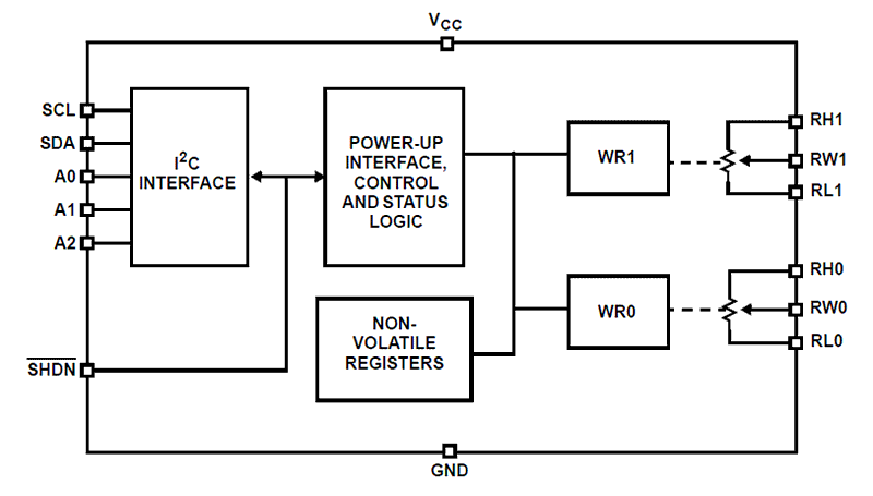
Description
The ISL22326WMVEP integrates two digitally controlled potentiometers (XDCP™) and non-volatile memory on a monolithic CMOS integrated circuit. The digitally controlled potentiometers are implemented with a combination of resistor elements and CMOS switches. The position of the wipers is controlled by the user through the I2C bus interface. Each potentiometer has an associated volatile wiper register (WR) and a non-volatile initial value register (IVR) that can be directly written to and read by the user. The contents of the WR control the position of the wiper. At power-up, the device recalls the contents of the two DCP's IVR to the corresponding WRs. The DCPs can be used as three-terminal potentiometers or as two-terminal variable resistors in a wide variety of applications including control, parameter adjustments, and signal processing. Device Information The specifications for an enhanced product (EP) device are defined in a vendor item drawing (VID), which is controlled by the Defense Supply Center in Columbus (DSCC). Hot links to the applicable VID and other supporting application information are provided on our website.
