Get to know this life changing technology: 5 of 5
USB PD specifications mark an important advance in the safety and convenience of USB charging. Manufacturers willing to implement these new features, however, must first read these specifications carefully and then undertake the extra work required to build these new capabilities into their products. It is not so easy to do so. Renesas provides solutions that greatly simplify the work required to build USB PD-compliant products.
Provides USB-C Power solution
Our last four sessions have taken us through USB PD and USB Type-C® technology.
Although USB Type-C and USB PD are well-designed for safety, convenient, and highly flexible, they are complex and difficult to implement. For example, even if only power provider or power consumer function is adopted, users should fully understand the USB Type-C and USB PD specification in order to properly utilize their high flexibility. Therefore, it significantly increases the hurdles to adoption. In addition, to ensure safety, overvoltage, overcurrent, and overheating conditions must be constantly monitored, and in the event of an abnormality, it must be handled in accordance with these specifications.
To solve this problem and easily develop products that implements USB PD feature, Renesas has provided a turnkey solution called the USB-C Power Solution that consists of a USB PD controller IC, power supply IC, battery management IC, etc. Here, the USB PD controller IC has responsibility for the communication and control of the USB PD. Power supply ICs have highly efficiency and they can input and output voltages defined by Power Rules (5V, 9V, 15V, 20V, 28V, 36V, 48V, and AVS). The battery management IC is called a fuel cage IC, which manages the battery status and ensures the safety of lithium-ion batteries. By simply using this USB-C Power solution, users can easily design products that implements USB PD. Additionally, we are striving to reduce the overall design resource as well as the resource of product hardware design by providing new firmware solutions.
Product Planning, and the steps for development
Here, we explain Renesas' USB-C Power solution from the perspective of the development steps.
When the product implements USB-C Power, the feature for power supply must be defined at the product planning stage. The feature for power supply refers to whether the product is the power provider (source: AC adapter, DC/DC module, etc.), the power consumer (sink: various handheld devices, etc.), or whether it supports both power provider and power consumer. (DRP: HUB, Power Bank, etc.). At the same time, the corresponding voltage and current values (power supply capacity for a source, power consuming request for a sink) will be determined.
Renesas offers USB-C Power turnkey solutions for power provider, power consumer, and both power provider and consumer. Customers can now easily adopt USB-C Power feature by using a Renesas USB-C Power solution that matches their system.
Development Steps
How to develop a product that has a USB-C Power port by using Renesas' USB-C Power turn-key solution is as follows.
Step 1: Get Renesas’ USB-C Power turnkey solution that matches the system.
The design kit (instruction manual, circuit drawing, BOM list, layout information) required for board design can be downloaded from Renesas.com.
Step 2: Check that the USB-C Power turnkey solution can perform as expected.
The USB-PD controller implemented on EVA board for the USB-C Power Turnkey Solution is preloaded with the basic firmware that is realized USB-PD operation. Therefore, many USB-PD functions can be realized simply by setting switches on the EVA board. USB-PD Functions that cannot be realized with only switch settings require updating the firmware, but we provide "VIDWriter" as a software solution that can be easily developed for that firmware.
Step 3: Develop an actual board incorporating USB PD using the design kit as a reference.
Implements USB PD function into the actual product by referring to the circuit drawing, BOM list, and layout information including in the design kit.
Step 4: Write the pre-evaluated firmware to the USB-PD controller on the actual board and check that it works expected.
Write the firmware evaluated in Step 2 to the USB-PD controller on the actual board developed in Step 3. Once you have confirmed that it works as expected, product development is completed.
The circuit drawing and layout information included in the design kit were developed by Renesas and their operation has been confirmed. Therefore, users can save a lot of man-hours by using circuit drawing in design kit rather than drawing a circuit while looking at the manual for the IC.
Renesas’ USB-C Power solution
Renesas offers the following USB-C Power turnkey solutions. We also have other turnkey solutions under development, so please feel free to contact us.
| Power Mode | Name | Reference Name | Description |
|---|---|---|---|
| Sink Only | Input Power Converter | RTK-251-SinkAdapter | This is a USB certified reference design to converts USB-C input power supplied by USB Type-C sourcing device to DC output. |
| Source Only | DC input module | RTK-251-BuckBoostConverter2 | This USB certified reference design converts a DC input to two USB Type-C source ports. |
| DRP | Power Bank | RTK-251-PowerBank3 | This USB certified single port power bank reference can connect 2 to 4 cells (default is 3 cells) in series and has a battery monitor function on this board. |
| DRP | Input/Output power converter | RTK-251-DRPEVB | This is the single port reference design that converts USB Type-C input power to DC output or DC input to USB Type-C output sourcing power. |
| Sink Only or DRP | Battery system | RTK-251-SinkCharger-ISL9238C | This is a single port reference design for implementing battery systems with 2 to 4 cells connected in series. This reference design supports Sink only mode and a mode that enables a power bank in combination with a lithium-ion battery with BMS. |
| Sink Only or DRP | Battery system | RTK-251-SinkCharger-RAA489118 | This is a single port reference design for implementing battery systems with 2 to 7 cells connected in series. This reference design supports Sink only mode and a mode that enables a power bank in combination with a lithium-ion battery with BMS. |
| Power Mode | Name | Reference Name | Description |
|---|---|---|---|
| Sink Only or DRP | 140W Battery system | RTK-G015-EPRSinkCharger-140W | This is a single port reference design for implementing battery systems with 2 to 7 cells connected in series. This reference design supports Sink only mode and a mode that enables a power bank in combination with a lithium-ion battery with BMS. |
Instruction tool "VIDWriter"
The instruction tool "VIDWriter" is provided as part of Renesas' USB-C Power solution. It informs the user how to set switches on the evaluation board of the USB-C Power turnkey solution and at the same time generates firmware for the final product.
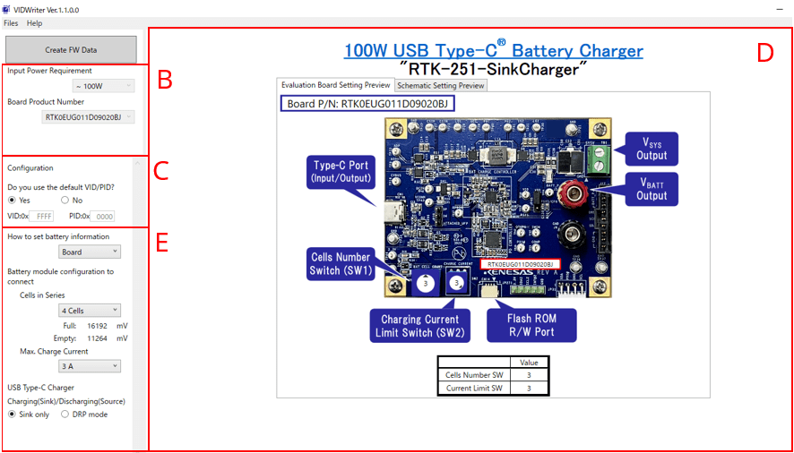
Figure 1: USB-C Power Solution Instruction Tool “VIDWriter”
When a customer selects a basic function in field B of Figure 1, the board picture that can achieve the expected function will be displayed in field D, and configurable items such as the voltage and current value to the board will be displayed in field E. In this example, field D displays the battery system reference. Here, if the customer sets the number of batteries connected in series and the maximum current in field E, the values of the switches that should be set on the board shown in field D will change accordingly. Customers can prepare to confirm the expected operation by setting the target switches on the actual board as shown on the screen. It is also possible to generate firmware with changed basic battery parameters (Full, Empty values), but, it is necessary to update the pre-installed basic firmware when customers use this tool.
As you can see, this tool allows customers to easily implement USB-PD functionality by simply setting the necessary parameters.
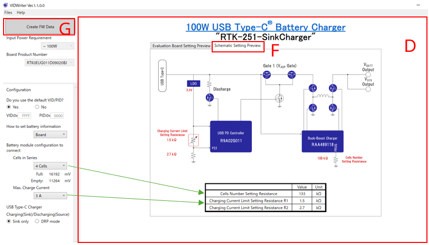
Figure 2: Resistance value display on the circuit drawing using the Instruction Tool “VIDWriter”
While the Renesas' USB-C Power solutions are easy to adopt with the design information and VIDWriter included in the design kit, they are intentionally limited in their flexibility. For example, we can support requests such as assigning LED control function to the unused pin of the PD controller R9A02G011. Please feel free to contact us.
Module List
- USB Power Delivery (1) Enhanced Convenience in USB Charging
- USB Power Delivery (2) The Technology - Convenience and Safety
- USB Power Delivery (3) The Technology 2 - USB Type-C and Role Swap
- USB Power Delivery (4) USB PD Safety Implementation
- USB Power Delivery (5) Faster Development with Renesas Solutions
Terms and Abbreviations
- AVS: Adjustable Voltage Supply. Specifications that allow Sink to require in 100mV steps for any output voltage of 9V or higher. This is similar to PPS.
- COLD Socket: No voltage applied to VBUS of USB connector
- DFP: Downstream Facing Port. A port that is mainly on PCs and is the initiator side of USB data communication.
- DRD: Dual-Role Data. Ports that can be either DFP or UFP.
- DRP: Dual-Role Power. Ports that can be either sources or sinks.
- EPR: Extended Power Range on Power delivery. Mode to achieve DC power supply exceeding 20V 5A.
- PD controller: Power Delivery Controller. It combines both TCPM and TCPC functions in one package, and it is responsible for the USB-PD communication and control.
- PDP: PD Power. Source output power. Used in Power Rules.
- Power Rule: Equipment design rules to ensure operation if "source power value (watt value) ≥ sink power value (same)"
- PPS: Program Power Supply. Specification that allows Sink to require any output voltage in 20mV steps and output current in 50mA steps.
- Sink: A device that consumes power from USB Type-C, such as a handheld device.
- Source: Device that supplies DC power, such as an AC adapter.
- SPR: Standard Power Range on Power delivery. Mode that realizes DC power supply of 20V 5A or less.
- TCPCI/TCPC: USB Type-C Port Controller Interface/ USB Type-C Port Controller. Defines only the low-level hardware required for USB-PD communication (TCPC) and TCPCI is communication specification for that device. Realizes PDC function in combination with TCPM.
- TCPM: USB Type-C Port Manager as described in TCPCI. Device or system that controls TCPC.
- Type-C: A connector defined by USB IF. Developed to realize the interchangeable insertion.
- UFP: Upstream Facing Port. A port that is mainly on peripheral device, and it is the responder side of USB data communication.
- USB: Universal Serial Bus
- USB-C: Universal Serial Bus Type-C®
- USB-IF: Universal Serial Bus Implementers Forum
- USB-PD: Universal Serial Bus Power Delivery
- USB PD controller: Same meaning as PDC