Overview
Description
[Notes] Renesas Emulator and Flash Memory Programmer Products with a USB Interface Notice Regarding Changes to Windows Driver Policy (PDF | English, 日本語)
USB driver for countermeasures (For E2, E2Lite, and IE850A only)
Topics
- The E2 emulator supports the new device RX14T.
The E2 emulator is an advanced on-chip debugging emulator and flash programmer developed with the concept of greater efficiency in development. The combination of its high-speed downloading and various software and hardware solutions will contribute to reducing development times.
Features
- High-speed download up to twice as fast as E1
The download speed is up to twice as fast as the E1 emulator. This substantially reduces waiting time for downloading the control programs to one-half at a maximum. - Hot plug-in function available without an optional adapter
Although the E1 emulator required an optional hot plug adapter sold separately to use the hot plug-in function, the E2 emulator does not need it. - Board interface compatible with that of E1
he E2 emulator can be connected to the user system that was designed for the E1 emulator because the pin arrangement to be connected to the user system has compatibility with the E1 emulator. [Learn More : the optional products for E2 ] - Support for new MCUs with next-generation cores
MCUs that have next-generation cores, such as those of the RH850/E2x series (which incorporate the G4MH core) or the RX66T group (which incorporate the new RXv3 core for the RX family) can be debugged. - Features for for RL78 and RX Families
- Support for the input and output of external triggers [Learn More: ToolNews]
For example, you can set up the stopping of programs or of the measurement of waveforms by simply using the test lead which comes with the E2 emulator to connect the emulator to an external measuring instrument with the CS+ integrated development environment or the e² studio integrated development environment. - Current Consumption Tuning Solution
In conjunction with the QE for Current Consumption, a dedicated tool for measuring current drawn, the E2 emulator is capable of the following items. These shorten the time taken to tune currents.- Measuring current with the E2 emulator alone
- Stopping a program when an excessive current is detected
- Visualizing the relationship between program operations and current
- Support for the input and output of external triggers [Learn More: ToolNews]
- Features for RH850 Family
- CAN Communications Time Measurement Solution
The following CAN-related tasks are possible in conjunction with the CS+ integrated development environment or the MULTI® integrated development environment (GHS MULTI) from Green Hills Software. This eases verifying the speed of CAN communications in terms of system requirements.- Measuring the reception processing time in CAN communications with the E2 emulator alone
- Stopping a program when the reception processing time exceeds the design value
- Visualizing the history of CAN communications
- Support for the input and output of external triggers [Learn More: ToolNews]
For example, you can set up the stopping of programs or of the measurement of waveforms by simply using the test lead which comes with the E2 emulator to connect the emulator to an external measuring instrument with the CS+ integrated development environment or the MULTI® integrated development environment (GHS MULTI) from Green Hills Software. - Software Trace Function [Learn More: ToolNews]
The function enables users to view the execution history of the programs such as the values of the program counter (PC) and the register values together with the debug instructions of MCUs for RH850 family with the CS+ integrated development environment or the MULTI® integrated development environment (GHS MULTI) from Green Hills Software. Using this feature, unlike the conventional method of “tracing data with the settings of events and conditions,” users can generate the execution history data such as the PC values and register values simply by inserting the debug instructions to the location where you like to check in the program.his feature is available in all RH850 family MCUs, including the ones do not have internal trace memory when debugging.
- CAN Communications Time Measurement Solution
- Learn More
Release Information
See the latest Release Information of MCUs.
RA Family RL78 Family RX Family RH850 Family R-Car Family RISC-V MCU
*Please contact Renesas sales division for RE Family.
Release Information for RA Family
| Purpose of use | Software to be used | Latest Version | Released | Operating Environment |
|---|---|---|---|---|
| On-chip Debugging | e² studio | (64-bit version) 2025-10 | Oct. 20, 2025 | Operating Environment |
| (32-bit version) V7.8.0 | Apr. 20, 2020 | |||
| Flash Programming | Renesas Flash Programmer V3 | V3.21.00 | Oct. 20, 2025 |
Please be aware that a User-system interface cable will need to be purchased separately to support RA device debug with E2 using 20-10 pins. Please see Optional Products for RA Family for details.
Release Information for RL78 Family
| Purpose of use | Software to be used | Latest Version | Released | Operating Environment |
|---|---|---|---|---|
| On-chip Debugging | CS+ (CS+ for CC) | V8.14.00Note1 | Jul. 22, 2025 | Operating Environment |
| e² studio | (64-bit version) 2025-10 | Oct. 20, 2025 | ||
| (32-bit version) V7.8.0 | Apr. 20, 2020 | |||
| IAR Embedded Workbench | A tool produced by Partner. For the details of support for E2, contact IAR Systems directly. | |||
| Flash Programming | Renesas Flash Programmer V3 | V3.21.00 | Oct. 20, 2025 | Operating Environment |
Release Information for RX Family
| Purpose of use | Software to be used | Latest Version | Released | Operating Environment |
|---|---|---|---|---|
| On-chip Debugging | CS+ (CS+ for CC) | V8.14.00Note1 | Jul. 22, 2025 | Operating Environment |
| e² studio | (64-bit version) 2025-10 | Oct. 20, 2025 | ||
| (32-bit version) V7.8.0 | Apr. 20, 2020 | |||
| IAR Embedded Workbench | A tool produced by Partner. For the details of support for E2, contact IAR Systems directly. | |||
| Flash Programming | Renesas Flash Programmer V3 | V3.21.00 | Oct. 20, 2025 | Operating Environment |
Release Information for RH850 Family
| Purpose of use | Software to be used | Latest Version | Released | Operating Environment |
|---|---|---|---|---|
| On-chip Debugging | CS+ (CS+ for CC) | V8.14.00Note1 | Jul. 22, 2025 | Operating Environment |
| e² studio | (64-bit version) 2025-10 | Oct. 20, 2025 | ||
| (32-bit version) V7.8.0 | Apr. 20, 2020 | |||
| IAR Embedded Workbench | A tool produced by Partner. For the details of support for E2, contact IAR Systems directly. | |||
| Green Hills Multi | A tool produced by Partner. For the details of support for E2, contact Green Hills Software directly. | |||
| Flash Programming | Renesas Flash Programmer V3 | V3.21.00 | Oct. 20, 2025 | Operating Environment |
Release Information for R-Car Family
| Purpose of use | Software to be used |
|---|---|
| On-chip Debugging | e² studio for R-CarNote1 |
Note
- e² studio for the R-Car family is included in the RoX Software Development Kit (SDK).
Release Information for RISC-V MCU
| Purpose of use | Software to be used | Latest Version | Released | Operating Environment |
|---|---|---|---|---|
| On-chip Debugging | e² studio | (64-bit version) 2025-10 | Oct. 20, 2025 | Operating Environment |
| Flash Programming | Renesas Flash Programmer V3 | V3.21.00 | Oct. 20, 2025 |
Please be aware that a User-system interface cable will need to be purchased separately to support RISC-V MCU device debug with E2 using 20-10 pins. Please see Optional Products for RISC-V MCU for details.
FAQ
Target Devices
Target Family
Downloads
|
|
|
|
|---|---|---|
| Type | Title | Date |
| Software & Tools - Other | E2 emulator Self Check Program V.1.02.00
|
|
| Software & Tools - Other | E2 emulator, E2 emulator Lite Linux driver
|
|
| Upgrade - IDE | USB Driver for Renesas MCU Tools V2.77.00 (for 64-bit version of Windows OS)
|
|
| Upgrade - IDE | USB Driver for Renesas MCU Tools(E2,E2 Lite,IE850,IE850A,PG-FP5) V2.77.00(for 32-bit version of Windows OS)
|
|
| Upgrade - Programmer | External Flash Definition Editor V.1.00 Release 01
|
|
|
5 items
|
||
Documentation
|
|
|
|
|---|---|---|
| Type | Title | Date |
| Flyer | PDF 400 KB 日本語 , 简体中文 | |
| Manual - Development Tools |
PDF
1.09 MB
日本語
This document is the User's Manual for the Renesas E2 emulator.
It is intended for developers who use the E2 emulator for program debugging.
The manual explains the product specifications, system configuration, connection methods, and usage limitations.
It covers the scope required to understand the hardware characteristics and how the E2 emulator is connected and used within its supported environment.
|
|
| Tool News - Note |
PDF
341 KB
日本語
This notice provides important information regarding the use of Renesas emulator products and flash memory programmer products equipped with a USB interface, as outlined below.
1. Products Not Affected by the Windows Driver Policy Change
2. Impact of the Windows Driver Policy Change on the E2 Emulator, E2 Emulator Lite, and IE850A, and Recommended Actions
3. Impact of the Windows Driver Policy Change on Other Emulator Products and Flash Memory Programmer Products
|
|
| Manual - Development Tools |
PDF
230 KB
日本語
This is a feature list summarizing the capabilities of Renesas' on-chip debuggers for each microcontroller. For the E2 Emulator, E2 Emulator Lite, E1 Emulator, E20 Emulator, MINICUBE2, E10A-USB, and E8a on-chip debuggers, it details the debugging capabilities supported for each corresponding microcontroller, including connection methods, break functions, trace functions, and more.
|
|
| Manual - Development Tools |
PDF
2.27 MB
日本語
This is the user's manual for the adapter that converts the user-system interface cable for the E2 emulator into a 14-pin, 2.54 mm pitch connector for connection to the target board. This manual contains information on the appearance, package contents, specifications, and usage.
|
|
| Manual - Development Tools |
PDF
1.11 MB
日本語
This is the user's manual for the adapter that converts the 14-pin connector for connecting the emulator's user-system interface cable to a 34-pin external trace connector when using the Emulation Adapter for the RH850 Family. This manual contains information on the appearance, package contents, specifications, etc.
|
|
| Manual - Development Tools |
PDF
2.28 MB
日本語
This is the user's manual for the user-system interface cable used to connect the E2 emulator to the 20-pin connector on the target board. This cable can also be used with the E2 emulator Lite and PG-FP6, and is included as standard with the E2 emulator. This manual describes the appearance, package contents, specifications, and usage instructions.
|
|
| Manual - Development Tools |
PDF
2.26 MB
日本語
This is the user's manual for the user-system interface cable used to connect the E2 emulator to the 10-pin connector on the target board. This cable can also be used with the E2 emulator Lite and PG-FP6. This manual contains information on the appearance, package contents, specifications, and usage.
|
|
| Application Note |
PDF
1.19 MB
日本語
This application note describes a library for controlling external flash memory connected to an RAmicrocontroller (hereafter referred to as “MCU”). By using the library introduced in this document, you canperform write and debug operations on the. external flash memory through an on-chip debugging emulator.
A sample project named “r20an0822ref0100-ra-refl.zip” (hereinafter referred to as “the Sample Project”) isavailable to facilitate the use of External Flash Library
|
|
| Manual - Development Tools |
PDF
881 KB
日本語
This is a supplementary manual to the emulator user's manual, summarizing important notes when debugging the RH850/U2B-E series using the E2 emulator, IE850A. It covers connection methods to the user system, functional overview, and usage precautions.
|
|
| Tool News - Note | PDF 154 KB 日本語 | |
| Tool News - Note | PDF 209 KB 日本語 | |
| Application Note |
PDF
1.87 MB
日本語
AI-generated Summary:
This document explains how to port projects from CS+ to e2 studio for the Renesas RX family using emulators such as E2 Lite, E2, and E20. It details the differences in emulator settings, connection configurations, and debugging operations within e2 studio. Users learn how to open CS+ projects in e2 studio, configure emulator connections via the Debug Configurations window, and manage target devices. The document covers debugging features including breakpoints, tracing, memory and register manipulation, and performance measurements, facilitating smooth migration and effective debugging in the e2 studio environment.
|
|
| Manual - Development Tools | PDF 2.03 MB 日本語 | |
| Manual - Development Tools | PDF 1.99 MB 日本語 | |
| Tool News - Note | PDF 259 KB 日本語 | |
| Tool News - Featured Tool | PDF 864 KB 日本語 | |
| Tool News - Notification | PDF 502 KB 日本語 | |
| Tool News - Release | PDF 205 KB 日本語 | |
| Manual - Development Tools | PDF 511 KB 日本語 | |
| Tool News - Note | PDF 142 KB 日本語 | |
| Tool News - Note | PDF 183 KB 日本語 | |
| Tool News - Release | PDF 176 KB 日本語 | |
| Tool News - Featured Tool | PDF 193 KB 日本語 | |
| Tool News - Notification | PDF 306 KB 日本語 | |
| Tool News - Notification | PDF 304 KB 日本語 | |
| Tool News - Notification | PDF 352 KB 日本語 | |
| Tool News - Release | PDF 92 KB 日本語 | |
| Tool News - Featured Tool | PDF 260 KB 日本語 | |
| Tool News - Note | PDF 141 KB 日本語 | |
| Tool News - Note | PDF 156 KB 日本語 | |
| Application Note |
PDF
1.17 MB
日本語
AI-generated Summary:
Main-core debugging enables secure development by separating secure programs running on the ICU-M core from non-secure programs on the main CPU core. It allows debugging of non-secure user programs while keeping secure information confidential. The method uses the E1/E20/E2/IE850A emulator and requires specific system configurations and authentication procedures. Key terminology includes integrated development environment, emulator debugger, host machine, target device, and user system. Manuals for the emulator provide hardware specifications, connection details, and usage notes essential for effective debugging.
|
|
| Application Note |
PDF
1.17 MB
日本語
AI-generated Summary:
Debugging methods focus on devices with an initially stopped CPU core and those transitioning to standby modes to optimize power consumption. Key capabilities include verifying core activation, measuring execution times for core activation and standby transitions, and restarting debugging at critical points such as core activation or MCU wake-up. Supported devices include various RH850 series MCUs. The document details environment setup, debugging configurations in CS+ and MULTI IDEs, and specific debugging techniques for different standby modes. It also covers precautions and terminology related to debugging and device operation.
|
|
| Manual - Development Tools | PDF 1.17 MB 日本語 | |
| Tool News - Note | PDF 243 KB 日本語 | |
| Manual - Development Tools | PDF 647 KB 日本語 | |
| Tool News - Note | PDF 150 KB 日本語 | |
| Tool News - Note | PDF 159 KB 日本語 | |
| Tool News - Note | PDF 92 KB 日本語 | |
| Application Note | PDF 2.25 MB 日本語 | |
| Application Note | PDF 1.82 MB 日本語 | |
| Tool News - Note | PDF 127 KB 日本語 | |
| Application Note |
PDF
2.09 MB
日本語
AI-generated Summary:
The document details a CAN communication time measurement solution using the E2 emulator and CS+ integrated development environment. It explains the setup, usage, and notes for measuring CAN bus communication processing times. The solution enables halting program execution when processing time exceeds a set value, aiding early diagnosis by reviewing trace data and communication history. It also defines key terms related to the emulator and development environment.
|
|
| Application Note | PDF 2.07 MB 日本語 | |
| Application Note | PDF 1.91 MB 日本語 | |
| Manual - Development Tools | PDF 340 KB 日本語 | |
| Manual - Development Tools | PDF 954 KB | |
| Manual - Development Tools | PDF 1.12 MB | |
| Manual - Development Tools | PDF 1.07 MB | |
| Manual - Development Tools | PDF 821 KB | |
| Tool News - Release | PDF 128 KB 日本語 | |
| Manual - Development Tools | PDF 683 KB 日本語 | |
| Manual - Development Tools | PDF 327 KB 日本語 | |
| Manual - Development Tools | PDF 1.73 MB 日本語 | |
| Application Note |
PDF
573 KB
日本語
AI-generated Summary:
The guide addresses common startup issues with the E1/E20 On-Chip Debugging Emulator. It explains warning messages about project file restoration due to version mismatches in CubeSuite+ and advises upgrading to the latest version. It highlights errors caused by missing CC-RX compiler installations and instructs users to install the compiler. The guide also details handling version differences in the CC-RX compiler, allowing debugging to continue if compatible or requiring version adjustments via the property panel.
|
|
| Manual - Development Tools | PDF 2.54 MB 日本語 | |
| Manual - Development Tools | PDF 178 KB 日本語 | |
| Application Note |
PDF
525 KB
日本語
AI-generated Summary:
The External Flash Definition Editor (EFE) enables creation of custom write programs for flash memory devices with unsupported command sets. Users customize sample C source programs, link header and library files, then create RFD and USD files for use with emulator software. The custom program must not exceed 8,192 bytes in memory size and 256 bytes in stack size. The development environment requires specific sample files, a suitable C/C++ compiler, and emulator tools.
|
|
| Manual - Development Tools | PDF 140 KB 日本語 | |
|
59 items
|
||
Design & Development
Sample Code
Sample Code
Filters
|
||
|---|---|---|
| Type | Title | Date Date |
| Sample Code | [Notes] Renesas Emulator and Flash Memory Programmer Products with a USB Interface Notice Regarding Changes to Windows Driver Policy - Sample Code
|
|
| Sample Code | RA Familly External Flash Library for tools
[Software=RA Flexible Software Package|v6.3.0],[Toolchains=GNU Arm Embedded|13.2.rel1]
ZIP
22 KB
Compiler:
GNU ARM Embedded
Function:
Debugging, Emulator, Memory, Programmer
IDE:
e2 studio
|
|
| Sample Code | [Notes] On-chip Debuggers E2 emulator and E2 emulator Lite (RA Connection) - Sample Code
|
|
3 items
|
||
Product Options
| Part Number | Status | Stock | Budgetary Price (USD) | Description |
|---|---|---|---|---|
| RTE0T00020KCAC1000J | Active | In Stock | 1ku | $25.88 | User-system Interface Cable for the E2 Emulator(20-10 pins) |
| RTE0T00020KCE00000R | Active | In Stock | 1ku | $445.88 | E2 Emulator |
Videos & Training
This video provides a step-by-step guide on using the E2 Self-Check Program (E2SCP) with the E2 emulator. With E2SCP, you can easily diagnose any hardware malfunctions in the E2 emulator.
Additional Details
Specifications
The supported facilities differ with the integrated development environment you are using.
| Item | Description |
|---|---|
| Since the method of connection and the functions may differ with the device you are using, refer to On-Chip Debugger Functional Overview (PDF | English, 日本語). |
| On-board programming | Supported |
| User interfaces | 14pin 2.54mm pitch connector (7614-6002: from 3M Japan, 2514-6002: from 3M Limited) 20pin 1.27mm pitch connector (FTSH-110-01-L-DV-K: from Samtec) 10pin 1.27mm pitch connector (FTSH-105-01-L-DV-K: from Samtec, FTSH-105-01-L-DV: from Samtec without a marking for matching the position of the connector; keying shroudNote1) |
| PC Interface | USB 2.0, full speed and high speed |
| Connection to the system | Connection to the system is via the user system interface cable which comes with the product (signals for connection vary with the type of the target MCU). |
| Operating voltage range | 1.8V to 5.5V (depends on the target MCU) |
| Power supply from Emulator | Supply current: Up to 200mA, Supply voltage: 1.8V to 5.0V |
| External dimensions (except for the protruding parts) | 105.9 mm×64.0 mm×19.5 mm |
| Compliance with overseas standards | European Standards: EN 55022 Class A, EN 55024 US FCC Standard: FCC part 15 Class A |
Note
- When using a connector without a guide marking (keying-shroud type), take care with regard to the direction for insertion of the cable.
Components
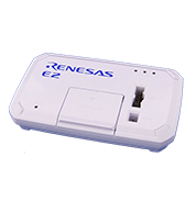
E2 Emulator Body
USB interface cable
*Bundled
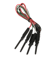
Test lead
*Bundled

User system interface cable 20-20 pins
*Bundled
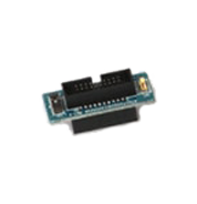
Conversion adapter 20 to 14 pins
*Bundled
Please be aware that a User-system interface cable will need to be purchased separately to support RA device or RISC-V MCU debug with E2 using 20-10 pins. Please see Optional Products for RA Family or Optional Products for RISC-V MCU for details.
Purchasing FAQ : Which user-system interface cable should be purchased when introducing an emulator? (E2 Lite/E2)
System Configuration
Refer to the Release Information in this page for information of software on PC.
Note
- Connection to the 20-pin connector of the E2 emulator is not supported. Use the 20-pin to 14-pin conversion adapter that comes with the E2 for connection to the 14-pin connector on the user system.
Optional Products
The following optional products are provided to facilitate the use of the E2 emulator in various ways. Please check which products are supported by your MCU..
RA Family RL78 Family RX Family RH850 Family R-Car Family RISC-V MCU
- Please contact Renesas sales division for RE Family.
- Please read references to "E1 emulator" in the manuals for optional products as also meaning "E2 emulator".
Optional Products for RA Family
| Type | Description | Product name / Manual |
|---|---|---|
| User-system Interface Cable | This cable is used to connect the E2 emulator. It can also be used for the E2 emulator Lite and PG-FP6. | User-system Interface Cable for the E2 Emulator (20-20 pins) RTE0T00020KCAC0000J (Bundled with the E2 Emulator) RTE0T00020KCAC0000J User's Manual User-system Interface Cable for the Emulator (20-20 pins) (PDF | English, 日本語) |
| User-system Interface Cable for the E2 Emulator (20-10 pins) RTE0T00020KCAC1000J RTE0T00020KCAC1000J User's Manual User-system Interface Cable for the Emulator(20-10 pins) (PDF | English, 日本語) | ||
| Isolator | Enables debugging in environments where the grounds of the user system and the host PC are not the same. | Isolator for the E2 Emulator (E2 Emulator Lite) of RA/RE RTE0T00020KCAA0000J RTE0T00020KCAA0000J User's Manual (Isolator for E2 Emulator) (PDF | English, 日本語) |
Optional Products for RL78 Family
| Type | Description | Product name / Manual |
|---|---|---|
| User-system Interface Cable | This cable is used to connect the E2 emulator. It can also be used for the E2 emulator Lite and PG-FP6. | User-system Interface Cable for the E2 Emulator (20-20 pins) RTE0T00020KCAC0000J (Bundled with the E2 Emulator) RTE0T00020KCAC0000J User's Manual User-system Interface Cable for the Emulator (20-20 pins) (PDF | English, 日本語) |
| Conversion Adapter | Converts the number and pitch of pins of the connector for connecting the emulator. | Small Connector Conversion Adapter for the E1 Emulator R0E000010CKZ11 R0E000010CKZ11 User's Manual (Small Connector Conversion Adapter for E1 Emulator) (PDF | English, 日本語) |
| 20-Pin to 14-Pin Conversion Adapter for the E2 Emulator RTE0T00020KCA00000R (Bundled with the E2 Emulator) RTE0T00020KCA00000R User's Manual (20-Pin to 14-Pin Conversion Adapter for the E2 emulator) (PDF | English, 日本語) | ||
| Isolator | Enables debugging in environments where the grounds of the user system and the host PC are not the same. | Isolator for the E1 Emulator R0E000010ACB20 R0E000010ACB20 User's Manual (Isolator for E1 Emulator) (PDF | English, 日本語) |
| Low voltage OCD BoardNote1 | Enables debugging of an MCU with a power-supply voltage such that the on-chip flash ROM cannot be reprogrammed.This product is used between the emulator and a user's system, and is united by the in-circuit connection with the user's system. | Low voltage OCD Board for RL78/G10 (10-pin/16-pin) R0E510Y47LVB00 Low voltage OCD Board for RL78/G10 (10pin, 16pin) Rev.1.00 (PDF | English, 日本語) An OCD board for debugging an RL78/G10 MCU (10-pin or 16-pin) with an adapter voltage below 4.5 V |
Note
- Target device: RL78/G10
Optional Products for RX Family
| Type | Description | Product name / Manual |
|---|---|---|
| User-system Interface Cable | This cable is used to connect the E2 emulator. It can also be used for the E2 emulator Lite and PG-FP6. | User-system Interface Cable for the E2 Emulator (20-20 pins) RTE0T00020KCAC0000J (Bundled with the E2 Emulator) RTE0T00020KCAC0000J User's Manual User-system Interface Cable for the Emulator (20-20 pins) (PDF | English, 日本語) |
| Conversion Adapter | Converts the number and pitch of pins of the connector for connecting the emulator. | 14-Pin to 38-Pin Conversion Adapter for the E1 Emulator R0E000010CKZ00 R0E000010CKZ00 User's Manual (14-Pin to 38-Pin Conversion Adapter for E1 Emulator) (PDF | English, 日本語) An adapter for converting the 14-pin/2.54-mm pitch connector on the head of the emulator user interface cable to a 38-pin/0.5-mm pitch connector |
| Small Connector Conversion Adapter for the E1 Emulator R0E000010CKZ11 R0E000010CKZ11 User's Manual (Small Connector Conversion Adapter for E1 Emulator) (PDF | English, 日本語) | ||
| 20-Pin to 14-Pin Conversion Adapter for the E2 Emulator RTE0T00020KCA00000R (Bundled with the E2 Emulator) RTE0T00020KCA00000R User's Manual (20-Pin to 14-Pin Conversion Adapter for the E2 emulator) (PDF | English, 日本語) | ||
| Isolator | Enables debugging in environments where the grounds of the user system and the host PC are not the same. | Isolator for the E1 Emulator R0E000010ACB10 R0E000010ACB10 User's Manual (Isolator for E1 Emulator) (PDF | English, 日本語) |
Optional Products for RH850 Family
| Type | Description | Product name / Manual |
|---|---|---|
| User-system Interface Cable | This cable is used to connect the E2 emulator. It can also be used for the E2 emulator Lite and PG-FP6. | User-system Interface Cable for the E2 Emulator (20-20 pins) RTE0T00020KCAC0000J (Bundled with the E2 Emulator) RTE0T00020KCAC0000J User's Manual User-system Interface Cable for the Emulator (20-20 pins) (PDF | English, 日本語) |
| Conversion Adapter | Converts the number and pitch of pins of the connector for connecting the emulator. | Small Connector Conversion Adapter for the E1 Emulator R0E000010CKZ11 R0E000010CKZ11 User's Manual (Small Connector Conversion Adapter for E1 Emulator) (PDF | English, 日本語) |
| 20-Pin to 14-Pin Conversion Adapter for the E2 Emulator RTE0T00020KCA00000R (Bundled with the E2 Emulator) RTE0T00020KCA00000R User's Manual (20-Pin to 14-Pin Conversion Adapter for the E2 emulator) (PDF | English, 日本語) | ||
| 14-Pin to 34-Pin Conversion Adapter for E2 emulator RTE0T00020KCA30000J RTE0T00020KCA30000J 14-Pin to 34-Pin Conversion Adapter (PDF | English, 日本語) Conversion Adapter included with Emulation Adapters | ||
| Isolator | Enables debugging in environments where the grounds of the user system and the host PC are not the same. | Isolator for the E1 Emulator R0E000010ACB20 R0E000010ACB20 User's Manual (Isolator for E1 Emulator) (PDF | English, 日本語) |
| Debug MCU Board / Emulation Adapter | Enables the in-circuit connection of the emulator with the user's system. Enables the use of enhanced debugging functions. | Debug MCU Board for RH850 Supported devices for Debug MCU Board for RH850 Family [On-chip Debugger] (PDF | English, 日本語) This board enables use of the trace function even if the target MCU does not have a trace function. The Debug MCU Board is for use in combination with a separately available 176-pin (with internal trace function) MCU of the RH850/F1L group. |
| Emulation Adapter for RH850 List of Emulation Adapter for RH850 Family (PDF | English, 日本語) This is an adapter mounting an emulation chip for G4MH Core RH850-family devices. In emulation of the device as a stand-alone unit, the internal tracing RAM is supported. Note that the E2 emulator does not support tracing via an Aurora interface. |
Optional Products for R-Car Family
| Type | Description | Product name / Manual |
|---|---|---|
| Conversion Adapter | Converts the number and pitch of pins of the connector for connecting the emulator. | 20-Pin(1.27mm) to 20-Pin(2.54mm) Conversion Adapter for the E2 Emulator RTE0T00020KCA10000R RTE0T00020KCA10000R User's Manual (20-Pin (1.27-mm Pitch) to 20-Pin (2.54-mm Pitch) Connector Conversion Adapter for the E2 Emulator (PDF | English, 日本語) An adapter for converting the 20-pin/1.27-mm pitch connector on the head of the emulator user interface cable to a 20-pin/2.54-mm pitch connector |
Optional Products for RISC-V MCU Family
| Type | Description | Product name / Manual |
|---|---|---|
| User-system Interface Cable | This cable is used to connect the E2 emulator. It can also be used for the E2 emulator Lite and PG-FP6. | User-system Interface Cable for the E2 Emulator (20-20 pins) RTE0T00020KCAC0000J (Bundled with the E2 Emulator) RTE0T00020KCAC0000J User's Manual User-system Interface Cable for the Emulator (20-20 pins) (PDF | English, 日本語) |
| User-system Interface Cable for the E2 Emulator (20-10 pins) RTE0T00020KCAC1000J RTE0T00020KCAC1000J User's Manual User-system Interface Cable for the Emulator(20-10 pins) (PDF | English, 日本語) |
Design Support
Resources
Support
Support Communities
- E2 emulator
Hi, I was using E2 emulator in my test system project. i have 3 number E2 emulator in my hand. i am try to flash with E2 emulator only one Emulator is properly working. other 2 emulator is not flashing properly. in that Renesas programmer says below error so if ...
Feb 23, 2024 - E2 Self Check FAILED (error 2200)
Hello Team, My E2 Self Check FAILED with below error, what could be the problem? *** E2 Self Check Program Log *** [Emulator] E2 [Serial Number] 3CS014456D [EML Board Ver.] 05 [E2_SCP Ver.] 1.02.00.000 [RFW Ver.] 1.01.00.000 [BFW Level0 Ver.] 1.06.00.000 [BFW ...
Jul 17, 2025 - Regarding choosing a emulators and debuggers for the development boards
Hi ,This is Amar and I am totally new to Renesas.I am working for a project which requires Renesas MCU and I wanted to get a clarification for purchasing emulators and debuggers for the following Renesas development boards.1.Renesas RL78/G13 2.Renesas RA4M2 development board and ...
Jun 30, 2025
Knowledge Base
- Why Does the Emulator Not Start on a Lower Power Supply Voltage? (E2, E2 Lite, E1) [RL78]
The possible cause is that the reset of the RL78 is not released because the LVD voltage set by the option bytes of the RL78 mounted on the target is higher than the new voltage. Start the emulator with the higher power supply voltage that was previously used. Then, write ...
Jun 13, 2022 - Error message: After connecting E1 emulator to RX MCU in CS+. (E2, E2 Lite, E1, E20)
This error message is displayed when the MCU is in the reset state and the RES# pin of the emulator connection connector is high. Check that the correct voltage is being supplied to the MCU (e.g. 3.3 V is not being input to an MCU which operates ...
Mar 3, 2021 - Unable to debug or write using the E2 Emulator (E2, E2 Lite, E1)
Check the switch of the 20-pin (1.27-mm pitch)/14-pin (2.54-mm pitch) connector conversion adapter. When using RH850, RX, set the switch to“1”. When using RL78, set the switch to “3”.
Mar 8, 2021

Support Communities


