Features
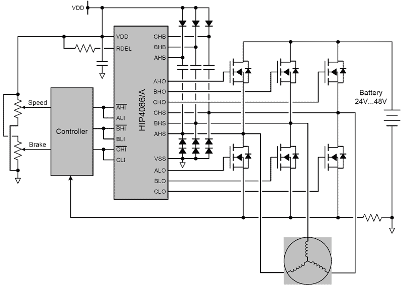
- Independently drives 6 N-channel MOSFETs in 3-phase bridge configuration
- Bootstrap supply maximum voltage up to 95VDC with bias supply from 7V to 15V
- 1.25A peak turn-off current
- User programmable dead time (0.5μs to 4.5μs)
- Bootstrap and optional charge pump maintain the high-side driver bias voltage.
- Programmable bootstrap refresh time
- Drives 1000pF load with typical rise time of 20ns and fall time of 10ns
- Programmable undervoltage set point
Description
The HIP4086 and HIP4086A (referred to as the HIP4086/A) are 3-phase N-channel MOSFET drivers. Both parts are specifically targeted for PWM motor control. These drivers have flexible input protocol for driving every possible switch combination. The user can even override the shoot-through protection for switched reluctance applications. The HIP4086/A have a wide range of programmable dead times (0.5μs to 4.5μs) which makes them very suitable for the low frequencies (up to 100kHz) typically used for motor drives. The only difference between the HIP4086 and the HIP4086A is that the HIP4086A has the built-in charge pumps disabled. This is useful in applications that require very quiet EMI performance (the charge pumps operate at 10MHz). The advantage of the HIP4086 is that the built-in charge pumps allow indefinitely long on times for the high-side drivers. To insure that the high-side driver boot capacitors are fully charged prior to turning on, a programmable bootstrap refresh pulse is activated when VDD is first applied. When active, the refresh pulse turns on all three of the low-side bridge FETs while holding off the three high-side bridge FETs to charge the high-side boot capacitors. After the refresh pulse clears, normal operation begins. Another useful feature of the HIP4086/A is the programmable undervoltage set point. The set point range varies from 6.6V to 8.5V.
Parameters
| Attributes | Value |
|---|---|
| Function | 3-Phase MOSFET Driver |
| Input Voltage Range (V) | 7 - 80 |
| Input Voltage (Max) (V) | 95 |
| VBIAS (Max) (V) | 15 |
| Quiescent Current | 40 µA |
| ISOURCE (Max) (mA) | 500 |
| ISINK (Max) (mA) | 1100 |
| Internal Buck Regulator | No |
| Gate Drive (V) | 15 |
| Internal Auxiliary Power | No |
| Adaptive Dead Time | No |
| VOUT Slew-rate Control | No |
| Charge Pump | Yes |
| Intern Gain Amplifiers | No |
| Internal Sample & Hold | No |
| Input Control | HI/LI |
| Input Logic Level | 3.3V/TTL |
| Advanced Fault Protection | Yes |
| Qualification Level | Standard |
Package Options
| Pkg. Type | Pkg. Dimensions (mm) | Lead Count (#) | Pitch (mm) |
|---|---|---|---|
| SOICW | 15.4 x 7.5 x 0.00 | 24 | 1.3 |
Application Block Diagrams

|
Multi-Functional Cordless Drill with Wire Detection
Cordless drill design with IoT enables wire detection, Bluetooth control, adjustable angles, and enhanced visibility.
|

|
48V BLDC Motor Position Control
Efficient BLDC motor system with precise control, rapid wake-up, and seamless component integration.
|
Additional Applications
- Brushless Motors (BLDC)
- 3-phase AC motors
- Switched reluctance motor drives
- Battery powered vehicles
- Battery powered tools
Applied Filters:

