Introduction to Digital Circuits: 1 of 3
In our next three sessions we look at digital circuits. Today, we’ll review the concept of digital, and look at the design of some fundamental digital circuits.
Analog vs. Digital: What’s the Difference?
Air temperature, sound loudness,light intensity—in nature, all of these quantities vary smoothly and continuously over a range. Such quantities is called "analog" value.
Today’s computers, in contrast, work with discrete quantities. These discrete quantities are called "digital" values. Where an analog measurement is a smooth curve that " looks like" the measured property, digital measurements are a series of discontinuous levels.
Here’s another way to put it: analog values are real numbers, whereas digital values are integers. Real numbers can represent any point on a number line, whereas integer are limited to express those special points evenly spaced on the line.
An analog circuit works with analog signals—where values change continuously. A digital circuit works with digital signals, where all values are discrete.
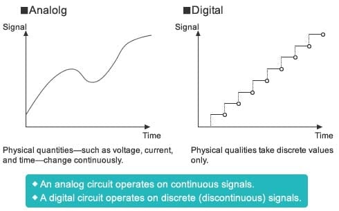
Figure 1 : Analog vs. Digital
To input nature’s analog information into digital circuits, it is first necessary to digitize the information: that is, to convert the analog signal into a digital signal. An analog/digital (A/D) converter samples the analog signal (reads the value at a set time interval), and converts each reading into a corresponding binary number (a base 2 value, expressed in 0’s and 1’s).
Since the converter is changing an analog signal that can take any fractional value into a digital signal that can take discrete values only, some information will be lost. Each analog reading must be rounded up or down to the nearest digital value. And since the converter reads the analog signal at a specific interval only, it loses the analog information that exists between these intervals.
As a result, digital values are only an approximation of the analog signal and always contain conversion error. This error can be reduced, however, by shortening the interval between measurements, and by using more precise (that is, longer bit-length) digital values.
But what’s the point of converting a smooth analog signal into a jumpy and imprecise series of numbers? There are at least two advantages: digital signals are much more resistant to noise; and, because modern computers work with digital values only.
Today’s powerful microcontrollers are capable of rapidly processing large volumes of digital information. These microcontrollers use digital circuits that take full advantage of the fact that, unlike analog signals, digital signals do not lose information during transmission and playback.
Binary Numbers
Digital signals typically express values using binary (also called " base 2" ) numbering, where each number is written using only 0’s and 1’s. Specifically, the rightmost digit of the number represents 20, the next digit to the left represents 21, then 22, etc. A four-digit binary number, therefore, can represent 16 values, from 0 to 15, as you can see in the Table 1. Values higher than 15 can be represented by adding additional digits, as necessary.
One advantage of treating digital signals as binaries is that it is easy to design logic circuits with binary output: the circuits are either ON or OFF, corresponding to the 1’s and 0’s of numeric binary numbers. The ON and OFF states are physically implemented as two voltage states: high (" H" ) and low (" L" ). In a typical CMOS IC with a 5-volt power source, " L" denotes a voltage from 0 up to 1.35 V, while " H" denotes a voltage from 3.15 V on up. Because 0 and 1 correspond to these relatively wide voltage ranges, the circuit produces the correct output even when there is moderate noise on the line.
| Decimal | Binary |
|---|---|
| 0 | 0000 |
| 1 | 0001 |
| 2 | 0010 |
| 3 | 0011 |
| 4 | 0100 |
| 5 | 0101 |
| 6 | 0110 |
| 7 | 0111 |
| 8 | 1000 |
| 9 | 1001 |
| 10 | 1010 |
| 11 | 1011 |
| 12 | 1100 |
| 13 | 1101 |
| 14 | 1110 |
| 15 | 1111 |
Table 1: Binary Representation of Decimal Values
Digital Circuits = Logic Circuits
A digital circuit, also called a logic circuit, carries out a logical operation. Three elemental circuits—AND, OR, and NOT—can be combined to build any desired logical operation.
Logic circuits are expressed using logical expressions and circuit symbols. (Here we use MIL symbols, although JIS symbols or other symbologies may be used instead.) A truth table indicates what the circuit’s output will be for all combination of inputs.
The AND Circuit, A Series Circuit
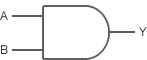
An AND circuit, also called a logical product circuit, take two inputs, and outputs a 1 if both inputs are 1, and a 0 otherwise.
Logical Expression of AND
Written using the " ・" operator. Example: Y = A・B
AND Circuit Notation
Truth Table
| A | B | Y |
| 0 | 0 | 0 |
| 0 | 1 | 0 |
| 1 | 0 | 0 |
| 1 | 1 | 1 |
Let’s look at how an AND circuit works. Figure 2 shows an AND circuit comprising two switches (SW A and SW B) and a LED indicator. Note that:
- SW A is On if input A is 1; SW A is Off if input A is 0.
- SW B is On if input B is 1; SW B is Off if input B is 0.
- LED Y is On (lit) if output Y is 1; LED Y is Off (dark) if output Y is 0
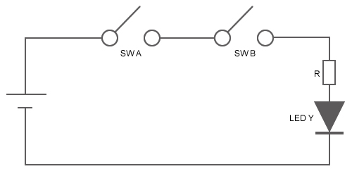
Figure 2: An AND Circuit
This AND circuit works as follows.
- If SW A and SW B are both On, then LED Y is On (lit).
- If one switch is On but the other is Off, then LED Y is Off (dark).
- If both switches are Off, then LED Y is Off (dark).
Basic logic circuits are also called gates. Note that you can control the value of the output by leaving one switch closed while controlling the other switch. Figure 2 illustrates the AND circuit’s gate operation.
- If either SW A or SW B is fixed at Off, the LED will remain dark; that is, the output will also be fixed at Off (the gate is closed).
- If either SW A or SW B is fixed at On, then the gate will output the value of the unfixed SW (the gate is open).
The OR Circuit, A Parallel Circuit
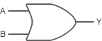
An OR circuit, also called a " logical sum circuit," outputs a 1 if either or both inputs are 1, and outputs a 0 if both inputs are 0. Example: Y = A+B.
Logical Expression of OR
Written using the " +" operator. Example: Y = A+B
OR Circuit Notation
Truth Table
| A | B | Y |
| 0 | 0 | 0 |
| 0 | 1 | 1 |
| 1 | 0 | 1 |
| 1 | 1 | 1 |
Figure 3 shows an OR circuit: a parallel circuit with two switches and one LED indicator.
- Since this a parallel circuit, the output will be On (LED Y will light up) if only SW A, only SW B, or both SW A and SW B are On.
The gate operation of the OR circuit is the reverse of the AND circuit’s operation.
- If either SW A or SW B is fixed at On, the LED will light; that is, the output will also be fixed at On (the gate is closed).
- If either SW A or SW B is fixed at Off, the gate will output the value of the unfixed SW (the gate is open)
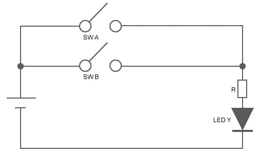
Figure 3: An OR Circuit
The NOT Circuit, An Inverter Circuit
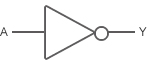
A NOT circuit (also called an " inverter circuit," ) takes only one input, and outputs the inverse of the input. If the input is 1, the output is 0. If the input is 0, the output is 1.
Logical Expression of NOT
Written using the " ¯" operator. Example: Y =![]()
NOT Circuit Notation
Truth Table
| A | Y |
| 0 | 1 |
| 1 | 0 |
Next time we will look at how digital ICs work.
Module List
- Elemental Digital Circuits
- Digital ICs/Combinational Logic
- Sequential Logic
Support

Support Communities

