概要
説明
本製品は日本国内では提供/サポートされていません。
This emulation pod is an MCU unit used in combination with the IE850. Hardware and software can be debugged efficiently in the development of systems in which the target device is used. The emulation pod can be easily disconnected. [Learn more]

ターゲットデバイス
追加詳細
仕様一覧
| 項目 | 内容 |
|---|---|
| Emulator supported | IE850 |
| Target MCUs | V850E2/DJ4 [μPD70F3522, μPD70F3523, μPD70F3524, μPD70F3525, μPD70F3526] V850E2/DP4-H [μPD70F3535, μPD70F3536, μPD70F3537] |
| Max. operating frequency | Same as target MCUs |
| Software break | 96 available (possibly reduced by breakpoints required by the debugger internally; usually 1) |
| Hardware break | Before: 4 points After: 8 points (triggered by Event) Access: 6 points (triggered by Event) * Ranges can be specified by 2 points. |
| Event detection | Post-execution: 8 points Access detection: 6 points Pass count: 4096 times Sequential: 4 steps |
| Exception event detection | Not available |
| Realtime trace | Trace range: 512K frames Trace data: Branch source/destination PC, access (DMA included) and time stamp Conditional trace: Section in combination with event detection, qualify and delay |
| Realtime RAM monitor | Available (DMA for debugging used) |
| Direct memory modification | Available (DMA for debugging used) |
| Execution time measurement | Start through end of execution Maximum, minimum, average pass count of 6 points (33bit counter) |
| Realtime profile | Available (by using trace, depending on the debugger used) |
| Coverage | C0 coverage |
| External trigger input/Event output | Not available |
| User system connection | Connected to the connecter mounted on the foot pattern of the MCU via an adapter. |
| Emulation pod external dimensions (mm) | 57(W) x 57(D) |
| Emulation pod weight | Approx. 40 g |
| Conformance with overseas standards | European Standards: EN 55022 Class A, EN 55024 US FCC Standard: FCC part 15 Class A |
コンポーネント
・エミュレーションPOD
ユーザシステムとの接続方法
画像
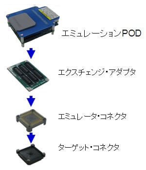
When designing a user system refer to the following descriptions in the users manual.
- Notes on designing users system
- External views of connectors and adapters
ターゲットデバイス
V850E2/DJ4 [μPD70F3522, μPD70F3523, μPD70F3524, μPD70F3525, μPD70F3526]
V850E2/DP4-H [μPD70F3535, μPD70F3536, μPD70F3537]


