Features
- Logic and Mixed Signal Circuits
- Highly Versatile Macrocells
- Read Back Protection (Read Lock)
- 1.8V (±5%) to 5V (±10%) VDD
- 1.8V (±5%) to 5V (±10%) VDD2 (VDD2 ≤ VDD)
- Operating Temperature Range: -40°C to 85°C
- RoHS-Compliant/Halogen-Free
- Macrocells Overview
- Four Analog Comparators (ACMP)
- Two Voltage References (Vref)
- Nineteen Combination Function Macrocells
- Three Selectable DFF/Latch or 2-bit LUTs
- One Selectable Continuous DFF/Latch or 3-bit LUT
- Four Selectable DFF/Latch or 3-bit LUTs
- One Selectable Pipe Delay or 3-bit LUT
- One Selectable Programmable Function Generator or 2-bit LUT
- Five 8-bit Delays/Counters or 3-bit LUTs
- Two 16-bit Delays/Counters or 4-bit LUTs
- Two Deglitch Filters with Edge Detectors
- State Machine
- Eight States
- Flexible Input Logic from State Transitions
- Serial Communications
- I2C Protocol Compliant
- Pipe Delay – 16 Stage/3 Output (Part of Combination Function Macrocell)
- Programmable Delay
- One Inverter
- Two Oscillators (OSC)
- Configurable 25kHz/2MHz
- 25MHz RC Oscillator
- Crystal Oscillator
- Power-On Reset (POR)
- Eight-Byte RAM + OTP User Memory
- RAM Memory Space that is Readable and Writable via I2C
- User-defined Initial Values Transferred from OTP

Description
The SLG46538 programmable mixed-signal matrix with asynchronous state machine and dual supply provides a small, low-power component for mixed-signal functions. The user creates their circuit design by programming the one-time programmable (OTP) non-volatile memory (NVM) to configure the interconnect logic, the I/O pins, and the macrocells of the SLG46538. This highly versatile device allows for a wide variety of mixed-signal functions to be designed within a very small, low-power single integrated circuit. The additional power supply (VDD2) on the SLG46538 provides the ability to interface two independent voltage domains within the same design. Users can configure pins, dedicated to each power supply, as inputs, outputs, or both (controlled dynamically by internal logic) to both VDD and VDD2 voltage domains. Using the available macrocells, designers can implement mixed-signal functions bridging both domains or simply pass through level translation in both High to Low and Low to High directions.
Parameters
| Attributes | Value |
|---|---|
| Nominal VDD | 1.71 - 5.5 |
| VDD2 (V) | 1.71 - 5.5 |
| GPIOs (#) | 16, 17 |
| Special Features | ASM (8 states) |
| ACMP Channels (#) | 4 |
| CNT/DLY (Max) (#) | 7 |
| LUTs (Max) (#) | 17 |
| D Flip-flops (DFFs) (#) | 8 |
| Pipe Delay | 16-stage |
| # of Programable Delays (#) | 1 |
| Oscillator Type | Conf. OSC, RC OSC, Crystal OSC, Conf. OSC, Ring OSC, Crystal OSC |
| Temperature Sensor (ch) (#) | 1 |
| Interface | I2C |
| Memory Type | OTP |
| Temp. Range (°C) | -40 to +85°C |
Application Block Diagrams
 | Low-Cost Smart Instrument Cluster Low-cost smart instrument cluster with single-chip design for efficient, custom LCD bike and vehicle displays. |
 | Level 2 EV Charger Modular EVSE system with advanced connectivity for efficient EV charging and management. |
 | 48V/3kW Motor Control for 2/3 Wheelers The 48V/3kW motor control system features a scalable inverter design, phase overcurrent fault detection, and ASIL-B safety. |
 | Robot Vacuum Cleaner This smart robot vacuum features environment mapping, anti-drop, obstacle detection, auto-recharge, app control. |
 | Entry-Class HMI Platform Entry‑class platform delivering reliable 64‑bit performance for modern HMI displays. |
Additional Applications
- Personal Computers and Servers
- PC Peripherals
- Consumer Electronics
- Data Communications Equipment
- Handheld and Portable Electronics
Complete Your Design
Explore complementary products to elevate your design
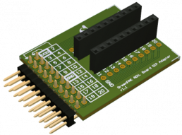
Renesas Boards & Kits

GreenPAK SLG46538 (STQFN-20) Development Kit with Socket Adapter
The SLG46538V-SKT is a socket adapter kit for use with the SLG4DVKADV GreenPAK™ Advanced Development Board or SLG4DVKLITE GreenPAK Lite Development Board. The SLG46538V-SKT includes the SLG4SA20DS-20x30 socket adapter and 50 SLG46538V (STQFN-20) GreenPAK programmable mixed-signal matrix IC... Read More
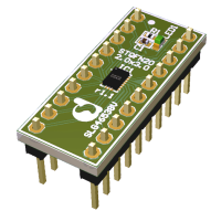
GreenPAK SLG46538 (STQFN-20) 20-Pin DIP Prototyping Board
The SLG46580V-DIP 20-pin DIP prototyping board is perfect for breadboarding and fast prototyping using the SLG46580 programmable mixed-signal matrix with asynchronous state machine and LDOs IC. It requires the SLG4SA-DIP DIP Adapter to use with the Advanced Development Board.
The GreenPAK™ DIP... Read More
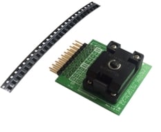
GreenPAK SLG46538 (MSTQFN-22) Development Kit with Socket Adapter
The SLG46538M-SKT is a socket adapter kit for use with the SLG4DVKADV GreenPAK™ Advanced Development Board or SLG4DVKLITE GreenPAK Lite Development Board. The SLG46538M-SKT includes the SLG4SA22DS-20x22 socket adapter and 50 SLG46538M (MSTQFN-22) GreenPAK programmable mixed-signal matrix IC... Read More
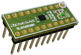
GreenPAK SLG46538 (MSTQFN-20) 20-Pin DIP Prototyping Board
The SLG46538M-DIP 20-pin DIP prototyping board is perfect for breadboarding and fast prototyping using the SLG46538M programmable mixed-signal matrix with asynchronous state machine and dual supply IC. It requires the SLG4SA-DIP DIP Adapter to use with the Advanced Development Board.
The GreenPAK... Read More
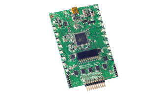
GreenPAK Advanced Development Board
The GreenPAK™ Advanced Development Board provides full programming, emulation, and testing functions for the GreenPAK programmable mixed-signal devices - for use with SLG46xxxX-SKT/SLG47xxxV-SKT socket kits.
The board works in tandem with the GreenPAK Designer software (built into the Go... Read More
Test This Board Remotely
GreenPAK DIP Adapter for GreenPAK Advanced Development Board
The GreenPAK™ DIP Adapter for the GreenPAK Advanced Development Board allows for using the SLG46xxxV-DIP and SLG47xxxV-DIP prototyping boards with the GreenPAK Advanced Development Board. It acts as the bridge between the advanced and DIP development platforms.
GreenPAK Serial Debugger Board (GSD)
The GreenPAK™ Serial Debugger (GSD) device can be used for programming GreenPAK programmable mixed-signal matrix IC products with multiple-time non-volatile memory (NVM) or for configuring the interconnect logic, the IOs, and the macrocells of all GreenPAK chips with an I²C interface. This... Read More

GreenPAK Lite Development Board
The GreenPAK™ Lite Development Board provides full programming, emulation, and testing functions for GreenPAK devices, working in conjunction with the Go Configure™ Software Hub. Board functionality is provided by the RX66T MCU from Renesas.

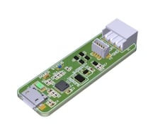
Universal USB Converter for USB-UART, USB-I2C, USB-I3C Demonstration Board
The QCIOT-USB2SERDEMOZ board is a USB-to-serial converter incorporating UART, SPI, I2C, and I3C, giving users the flexibility to connect to the desired serial communication protocol to communicate to the device via a PC using a simple terminal interface. In addition to transparent mode, the... Read More
