Features
- 60V maximum bootstrap supply voltage
- 3.3V and 12V LDOs with dedicated enable pins (HIP2104)
- 5µA sleep mode quiescent current
- VDD undervoltage lockout
- 3.3V or 5V CMOS compatible inputs with hysteresis
- Integrated bootstrap FET (replaces traditional boot strap diode)
- HIP2103 is available in a 3x3mm, 8 Ld TDFN package
- HIP2104 is available in a 4x4mm, 12 Ld DFN package
- Pb-Free (RoHS Compliant)

Description
The HIP2103 and HIP2104 are half-bridge drivers designed for applications using DC motors, 3-phase brushless DC motors, or other similar loads. The two inputs (HI and LI) independently control the high-side driver (HO) and the low-side driver (LO). HI and LI can be configured to enable/disable the device, which lowers the number of connections to a microcontroller and the cost. The low IDD bias current in the Sleep Mode prevents battery drain when the device is not in use, which eliminates the need for an external switch to disconnect the driver from the battery. Integrated pull-down resistors on all of the inputs (LI, HI, VDen, and VCen) reduce the need for external resistors. An active low resistance pull-down on the LO output ensures that the low-side bridge FET remains off during the Sleep Mode or when VDD is below the Undervoltage Lockout (UVLO) threshold. The HIP2104 has a 12V linear regulator and a 3. 3V linear regulator with separate enable pins. The 12V regulator provides internal bias for VDD and the 3. 3V regulator provides bias for an external microcontroller (and/or other low voltage ICs), which eliminates the need for discrete LDOs or DC/DC converters.
Parameters
| Attributes | Value |
|---|---|
| Bootstrap Supply Voltage (Max) (V) | 60 |
| VBIAS (Max) (V) | 14 |
| Peak Pull-up Current (A) | 1 |
| Peak Pull-down Current (A) | 2 |
| Turn-On Prop Delay (ns) | 23 |
| Turn-Off Prop Delay (ns) | 27 |
| Rise Time (μs) | 0.021 |
| Fall Time | 17 |
| Temp. Range (°C) | -40 to +125°C |
| Input Logic Level | 3.3V/TTL |
| Qualification Level | Standard |
Package Options
| Pkg. Type | Pkg. Dimensions (mm) | Lead Count (#) | Pitch (mm) |
|---|---|---|---|
| DFN | 4.0 x 4.0 x 0.90 | 12 | 0.5 |
Application Block Diagrams
 | Wi-Fi Connected Garage Door Controller Wi-Fi garage door controller offers smartphone control in SoftAP mode and easy prototyping options. |
 | Versatile Motor Control for Power Tools MCU-powered motor control boosts performance, simplifies design, and enhances power tool efficiency. |
 | Smart BLDC Ventilation Fan Smart BLDC fan controller improves air quality, cuts energy costs, and detects VOCs, moisture, and CO2. |
Additional Applications
- Half bridge, full bridge and BLDC motor drives
- UPS and inverters
- Class-D amplifiers
- Any switch mode power circuit requiring a half bridge driver
Complete Your Design
Explore complementary products to elevate your design
Renesas Boards & Kits

60V, 1A/2A Peak Half-Bridge Driver with 4V UVLO Evaluation Board
The HIP2103_4MBEVAL1Z is an evaluation board for the HIP2103 and HIP2104 half‑bridge MOSFET drivers. The tool consists of a motherboard and the HIP2103DBEVAL1Z and HIP2104DBEVAL1Z evaluation daughter cards. The motherboard includes an on‑board microcontroller used to generate the appropriate... Read More
60V, 1A/2A Peak Half-Bridge Driver with 4V UVLO Demonstration Board
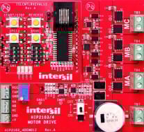
The HIP2103‑4DEMO1Z is a demonstration board with a microprocessor‑based controller used to evaluate the features of the HIP2103 and HIP2104. It supports three motor‑drive topologies: three‑phase operation for brushless DC (BLDC) motors, and full‑bridge and half‑bridge configurations for... Read More

3-Phase 1/2 Bridge Driver Demonstration Board
The HIP2103-4DEMO2Z module is a prototyping tool that uses the HIP2103 and the HIP2104 half-bridge drivers to control six on-board MOSFETs configured as a 3-phase bridge. This module is intended to drive a BLDC motor, but can be used in any application that requires any combination of 3... Read More
