Features
- Power supply voltage (VIN) 4.0V to 5.5V
Selectable output voltage range for 4 bucks:- CH1 Buck: 2.1V to 3.3V, 20mV step, 1.5A
- CH2 Buck: 1.5V to 2.6V, 20mV step, 1.5A
- CH3 Buck: 0.9V to 1.3V, 5mV step, 1.5A
- CH4 Buck: 0.8V to 1.4V, 5mV step, 5.0A
- LDO:
- VOUT: 3.3V
- IOUT: 0.2A (max)
- General-purpose ADC:
- 8-bit SAR ADC
- Two external inputs
- Die temperature sense
- Protection functions:
- Overcurrent protection
- Overvoltage protection
- Undervoltage protection
- Thermal shutdown protection
- I2C control interface:
- Standard mode (100kbit/s)
- Fast mode (400kbit/s)
- Fast mode+ (1Mbit/s)
- Package: QFN32 5.0mm x 5.0mm

Description
The DA9080 is a five-output configurable power management IC (PMIC) that has four synchronous step-down buck regulators and one 200mA LDO. One of the bucks is capable of up to 5A of output current. Robust protection features include undervoltage lockout (UVLO), overcurrent protection (OC), and thermal protection for fault protection features. The DA9080 is offered in a 32-lead QFN package.
Benefits
- Drives various Arm® cores with configurable powerful power rails
- Excellent input/output and efficiency characteristics minimize board area
- Complete supervision functions (UVLO, OC, OV, UV, TSD, PG) improve system stability
Parameters
| Attributes | Value |
|---|---|
| Qualification Level | Standard |
| Product Type | MPU |
| Processor Supplier | Renesas |
| Processor Name | RZ G2H, G2M, G2N, N2H, T2H, T2M, N2L, T2L, T2N, A3M |
| Total step-down DC/DC converter channels (#) | 5 |
| Step-up DC/DC converter Channels (#) | 0 |
| Input Voltage (Min) (V) | 4 |
| Input Voltage (Max) (V) | 5.5 |
| Bus Voltage (Max) (V) | 5.5 |
| Output Current Max (A) | 5 |
| Outputs (#) | 5 |
| Function | 5-ch PMIC |
| Comm. Interface | I2C |
| Battery Interface | No |
| GPIOs (#) | 0 |
| Integrated Battery Charger | No |
| Switching Frequency (MHz) | 2 - 2 |
Application Block Diagrams
 | Human Machine Interface (HMI) for Appliances Customizable HMI system for smart appliances with display, touch, voice, and NFC options. |
 | Dexterous Robotic Hand Modular, high‑precision motor control architecture for scalable dexterous robotic hands. |
 | 6‑ and 9‑Axis Industrial Motor Control with Ethernet High-precision and efficient 6- and 9-axis motor control designed for robotics and industrial applications. |
 | Multi-Protocol Network System for Building Automation Multi-protocol network system collects data from various building automation systems and incorporates industrial communication technologies. |
 | Motor Control System with Industrial Network and Functional Safety This motor control system integrates MPU and MCU for efficient industrial motor control and networking. |
Additional Applications
- Single board computers
- Lower power processors
- Test equipment
- POS terminals
Complete Your Design
Explore complementary products to elevate your design
Renesas Boards & Kits
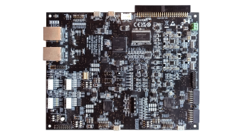
RZ/T2M & RZ/T2L Safety Motor Control Demonstration Kit
The RZ/T2M & RZ/T2L Safety Motor Control Demonstration Kit offers valuable insights into the hardware requirements for achieving SIL3 functional safety in motor drives. This kit delivers an out-of-the-box experience for RZ/T2L functional safety, including support for safety networks, powered by... Read More
Partner Boards & Kits
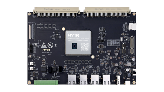
MYC-YT2HX System on Module (SoM)
RZ/A3M Feather System on Module (SoM)
Support Communities
-
DA9080 power VDDIO from LDO output
I am designing a board using the Renesas DA9080 multistage buck + LDO IC. The VDDIO pin requires a 3.3V level for I2C communication, and I was wondering if it is possible to power this line with the LDO output pin from the chip itself, or if I need a ...
Sep 6, 2024 -
DA9080 demo/eval board
Is there a demo/eval board for the DA9080? I want to use it in a design that has to be completed quickly so I have to prove functionality first. Thanks, -Jacob
Oct 26, 2024 -
PMIC IC for R9A07G075M24GBG#AC0
Hi Team We are planning to use R9A07G075M24GBG#AC0 in our design, because of the space constraints in our board we can't go ahead with multiple DC-DC convertors. Please suggest any suitable PMICs.
Feb 28, 2024
Knowledge Base
-
RZ/A3M: Are there any recommended power management IC (PMIC) for RZ/A3M?
PMIC DA9080-62 is recommended.
May 19, 2025

Support Communities


