Features
- 32MHz Arm® Cortex®-M0+ CPU
- For control applications that require low power operation modes and fast wake-up times
- Memory Protection Unit (MPU) for additional safety and security
- Digital Addressable Lighting Interface (DALI)
- Smart mix of analog and digital peripherals
Description
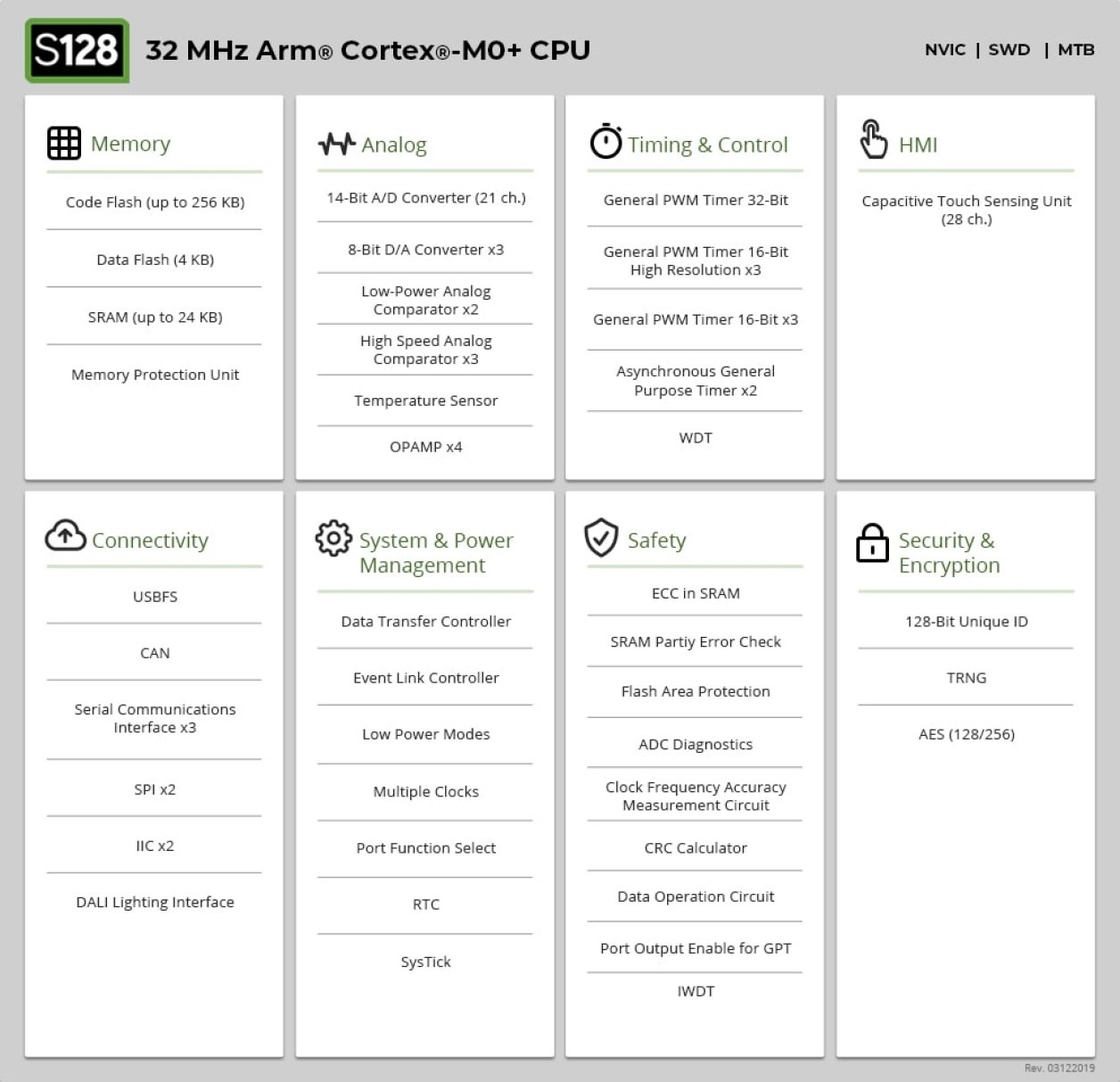
Uniquely suited for control applications that require low power operation modes and fast wake-up times, the S128 MCU Group has 256KB of flash memory and 24KB of SRAM. It includes a Memory Protection Unit (MPU) for additional safety and security, a Digital Addressable Lighting Interface (DALI), and a smart mix of analog and digital peripherals.
Commercial software worth over $100K which is available to developers using the Synergy Platform for no charge and with unlimited production license rights. The production-ready SSP is fully tested, maintained, and supported by Renesas.
Parameters
| Attributes | Value |
|---|---|
| Program Memory (KB) | 256 |
| RAM (KB) | 24 |
| Carrier Type | Tray |
| Supply Voltage (V) | 1.6 - 5.5 |
| I/O Ports | 24, 28, 37, 53 |
| Temp. Range (°C) | -40 to +85, -40 to +105 |
| Operating Freq (Max) (MHz) | 32 |
| Sub-clock (32.768 kHz) | No |
| On-chip Oscillator | No |
| Ethernet (ch) | 0 |
| EtherCat (ch) (#) | 0 |
| SCI or UART (ch) | 0, 3 |
| CAN (ch) | 1 |
| CAN-FD (ch) | 0 |
| PWM Output (pin#) | 0 |
| 32-Bit Timer (ch) | 1 |
| 16-Bit Timer (ch) (#) | 3, 4, 6 |
| 8-Bit Timer (ch) | 0 |
| Standby operable timer | No |
| 16-Bit A/D Converter (ch) | 0 |
| 14-Bit A/D Converter (ch) | 10, 13, 15, 21 |
| 12-Bit A/D Converter (ch) | 0 |
| 10-Bit A/D Converter (ch) | 0 |
| 12-Bit D/A Converter (ch) | 0 |
| 8-Bit D/A Converter (ch) | 3 |
| Capacitive Touch Sensing Unit (ch) | 0 |
| Graphics LCD Controller | No |
| Security & Encryption | 128-bit Unique ID, TRNG, AES128, AES256 |
Application Block Diagrams
 | DALI RGBWW LED Driver DALI 2.0 RGBWW LED driver for driving 5 LED strips via Synergy MCU and 24V boost. |
Additional Applications
- Industrial Flow Measurement
Applied Filters:

