Overview
Description
The PowerCompass tool helps users quickly identify parts that match their specific requirements, set up multiple rails, perform high-level system analysis, and generate custom reference design files. The PowerCompass™ multi-rail configuration tool is available exclusively as a web app, however, users can work offline using the web app.
How to Use PowerCompass
Define your system input and output requirements. You can build a system from scratch, or you can choose from over 300 templates covering MCU/MPUs and popular FPGA platforms.
2. Select Parts
Once you’ve got your rails identified, suggested parts are just a click away — including both single and multi-output devices.
The app looks at the efficiency data across your specified output range and presents system cost and graphs showing the system efficiency, power dissipation, and junction temperature.
For schematic-enabled parts, you can generate customized reference design files to get a BOM and a set of base schematics with all the associated blocks connected together.
Features
- Start from scratch, or use templates for FPGA, MCU, etc.
- Enter inputs/outputs/specs and get suggested parts
- Compare and select devices
- Get high-level summary analysis
- Generate reference design files
- Automatically build block diagram
- Part Selector (manual + competitor cross reference)
- Load/save project files
- Ability to drag to re-order rails
- Mobile support
- Import Xilinx and Altera Power Estimator files
- Advanced sequencing support
- Offline mode
- Connect to iSim simulation tool
Target Devices
Support

Support Communities

Knowledge Base

Videos & Training
Start your design from a template, FPGA Power Estimator file, saved project or from scratch.
PowerCompass Detailed Instructions
Select a Template or Start from Scratch
You can build a system from scratch, you can import an FPGA vendor (e.g., Xilinx, Altera) power estimator file, or you can choose from over 300 templates covering popular FPGA platforms such as Xilinx, Altera, Lattice, and Microsemi/Actel, and an expanding portfolio of Renesas microcontrollers.
These templates help you get started on your design by providing the most common rail configurations. You can change any of the parameters as needed to match your actual design.
Contact us if you'd like to request a new template to be added.
You can also open a previously saved project.
How to Import Xilinx Power Estimator Files
- Open your Xilinx Power Estimator Excel Spreadsheet and export the contents to a .pwr file.
- Select the Use Project Template or File choice from the Start screen.
- Either browse the files on your computer or
- Drag the .pwr file from your computer into the browser window.
How to Import Altera Files
The Altera power estimator file is generated as a large .XLS file with multiple worksheets, which can cause some older browsers to process the file very slowly. If you are experiencing long loading times, please save the file as a .CSV file for faster processing.
1. Open the Power Estimator File in Excel.
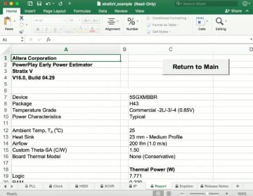
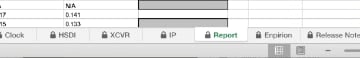
2. Select the Report tab to make it the active sheet.
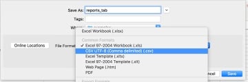
3. From the File menu, select Save As and choose CSV (comma separated value) as the file type from the drop-down menu. Choose Save Active Sheet if prompted.
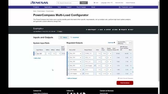
Specify Rail Requirements
Configure a complete power map of your system by entering your system input and output rail specifications, current requirements, sequencing, and more.
- Enter your system input voltage and current specifications. If you selected a template, the input, output and current specifications are already filled in.
- Rename rail names and outputs to match system names as desired.
- Select a source rail for your output using the drop-down box in the Output Rails section. This source rail can either be a system Input Rail or an output of another regulator, indicated by this icon:
- Enter your output regulator specifications as needed, including the sequencing if needed. Additional options are found under the More column:
- Select Power Good to show only parts that include power good support
- Select Enable Pin Input to show only parts that include an enable pin
- Select LDO to limit results for that rail to linear regulators only. Note: if you select LDO, the Sync options will automatically be disabled.
- Select Sync Input or Sync Output to only show parts with sync options. Note: not available if you choose the LDO option.
- The system keeps track of power requirements at each input rail and output regulator by using the overall Assumed Minimum Efficiency (default = 85%), which can be adjusted as needed by typing in a new value in that field.
- Tap Find Solutions to see suggested part results
Block Diagram Interface
You can also specify your rail requirements using the Block Diagram view. You can switch between the Table view and the Diagram view. Changes made in either interface are automatically updated in the other interface.
- Tap the Diagram selection near the top of the screen.
- Tap Add a Rail to create a new system rail, or tap Add an Output to add a new output rail.
- Tap the Expand icon to see the diagram in full screen, or use the Zoom in/out buttons to zoom into details of the diagram.
- Tap the PNG icon to save an image of the diagram to your computer.
Select from Suggested Parts
- Results are grouped by Topology (Mixed, Analog, Analog Integrated FET, Analog Module, Digital, Digital Integrated FET, or Digital Module)
- Tap the Output rail to see suggested parts for that rail, or choose Expand All to see suggestions for all rails.
- Sort results by tapping the column header. A red arrow indicates the column being sorted, and the sorting order.
- Limit or expand the number of results per Topology (default is 5; there's no practical limit) to see more or fewer results in each section.
- Dual output options are shown with the rail names connected; single outputs are shown below the dual output options.
- If you intend to generate a reference design, look for parts that are schematic enabled, indicated with this icon:
- Important: You must select at least one part per output rail in order to continue. You can select as many parts as you want per rail, and you'll be able to compare the performance among the parts in the next step.
- Tap Continue to generate a summary analysis to help you fine tune your design.
Refine System Settings and Compare Parts
On the Compare and Select screen, graphs modeling the system efficiency and power dissipation appear at the top of the page, and the estimated system cost (based on 1k pricing) appears at the bottom of the output table. If you selected multiple parts for an output in the previous step, you'll see a drop-down menu that allows you to switch parts. As you select parts, these summary graphs and costs will dynamically update.
- For each output, tap the Output summary row or the plus icon to see detailed graphs.
- You can change the default values for Light Load, Typical Load and Max Load to best represent the system you are designing for.
- Tap the part number above the graph to show/hide the chart lines for that part. Note: showing/hiding parts on the graph does not affect which part is selected for the output; use the drop-down menu on the output summary row to select the parts for the output.
Generate Reference Design
Once you have chosen the devices that best work for your system, you can generate customized reference design files to get a BOM and a set of base schematics with all the associated blocks connected together. Only schematic-enabled parts will be included, indicated with this icon:
- Tap the Generate Reference Design button at the top or bottom of the page
- Type in a name for your project. This name will be added to your custom reference design files, so shorter is better.
- Sign in (or register if you don't have an account) if you're not already signed in
- Tap Continue to generate your custom reference design files.
You'll see an animation on the screen as your files are generated. Once complete, the files will appear on the web page, and they will be emailed to the email address listed on your Renesas.com account. This email will also contain a link where you can download the files for a limited time.
Working with Projects
You can save a project, then edit, copy or delete that project. You can also send projects to another user.
Save Project
- From anywhere in the project, tap Save from the top menu.
- If you are not signed in, you will be prompted to sign in to your Renesas.com account.
- Name the project with a unique name.
Open a Saved Project
Completed projects are projects that have a reference design generated. In progress projects do not have a reference design.
Note: you must be signed in to view a list of your saved projects.
- Sign in to your Renesas.com account.
- From the main starting screen, tap the project you want to open, and tap the Continue button.
- Alternately, choose the Projects option from the top menu.
Edit Project
Note: once a reference design has been generated, you can no longer edit the project. You will need to copy the project and edit the copied version.
- Choose the Projects option from the top menu.
- For In Progress projects, tap Edit next to the project you want to edit. Then make any edits you wish to make. Tap Save when finished.
- For Completed projects, tap Copy and Edit next to the project you want to edit. Make any edits you wish to make. Tap Save when finished.
Delete Project
- Choose the Projects option from the top menu.
- Tap Delete next to the project you want to delete, and confirm the deletion.
Send Project
You can send a project to another user (or even yourself). All selections are saved, including any reference designs that are generated.
- From within a project choose Send from the top menu.
- Enter the email address of the user where you want to send the project.
- Alternatively, choose the Projects option from the top menu, then tap Send next to the project you want to send. Enter the email address of the user where you want to send the project.
Receive Sent Project
When a user sends you a project, you can review the details without saving. If you want to keep the project for later use, you must save it in your own list of projects.
- Tap on the link from the email sent from the system.
- Once the project is open, tap Save from the top menu.
Offline Support
You can perform many tasks offline, and then sync your projects when you are back online.
Note: offline access is supported in Chrome and Firefox only.
Disabled Offline Activities
The following activities are not available in offline mode:
- You cannot load saved projects.
- You cannot generate a reference design.
How to Work Offline
- If your computer loses Internet access, the PowerCompass tool will automatically switch to Offline mode.
- You can force your browser to offline mode by clicking on the Online button, and selecting Switch to Offline Mode.
Note that you will need to visit the PowerCompass tool at least once prior to going offline in order to download the part data. - If you know you will be working offline, you can force the tool to refresh the data by selecting Refresh Offline Data before going offline.
- When you are ready to start working online, select Switch to Online Mode by tapping the Offline button in the header of the tool.