概要

説明

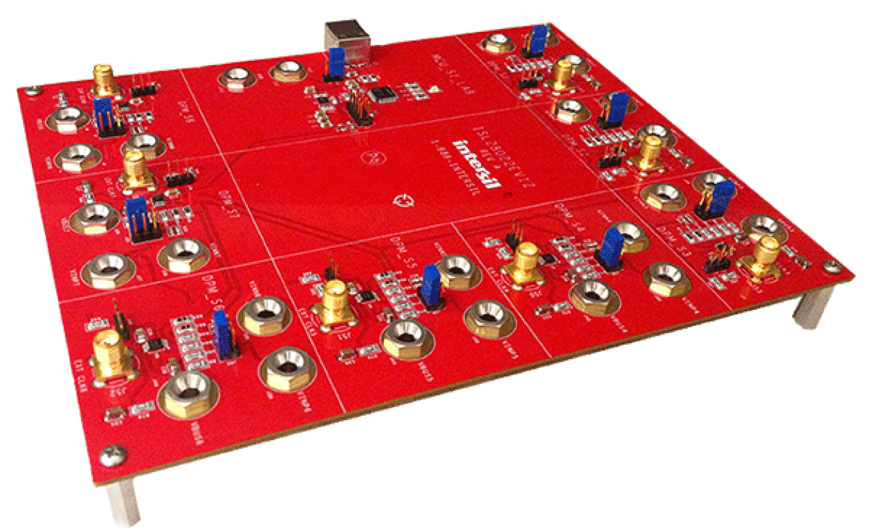
The Digital Power Monitor (DPM) 8 site evaluation board demonstrates the functionality and performance of the ISL28022. By design, the ISL28022 is considered a digital helper for a variety of applications ranging from energy optimization to diagnostics of complex systems. The design of the DPM evaluation board is generic such that the customer can embed the monitor into their specific application.

The DPM Evaluation kit is accompanied by a graphical user interface (GUI) that allows the user to configure the ISL28022 for monitoring bus voltage and current in a specific application. The GUI has a data save feature allowing the transfer of measurement data to another software application for analysis.

The ISL28022EV1Z evaluation board has 8 sites/channels with one microcontroller that is responsible for the data transaction and configuration for each DPM. The ISL28022 is a slave to the microcontroller via a single I2C/SMBus interface. The ISL28022 has two address pins that allow for 16 individual DPMs to be connected on a single I2C bus. The evaluation board utilizes 8 of the available 16 addresses of the ISL28022.

特長

  • Current Sense
    • High-side or low-side (RTN) Sensing
    • Bidirectional current sensing
  • Wide Input Voltage Sense Range: 0V to 60V
    • Handles negative system voltage
  • 16-bit ΣΔ ADC Monitors Current and Voltage
    • Voltage measuring error: <0.3%
    • Current measuring error: <0.3%
    • Internal 500kHz clock and adjustable sample rate from 72μs to 64ms
    • External Clock Sync available
  • Over/Under Voltage and Over Current Fault Monitoring
    • Interrupt output pin available
  • I2C/SMBus interface
    • Supports high-speed I2C: 3.4MHz
    • 16 slave addresses
    • Broadcast I2C measurement command available
  • VCC Range: 3V to 5.5V
  • ICC: 700μA
  • ESD (HBM): 8kV

アプリケーション

アプリケーション

  • Telecom/Datacom
  • Routers and Servers
  • Battery Management/Charging
  • Power Distribution
  • Smart Power
  • DC/DC, AC/DC Converters
  • Automotive
  • Medical and Test Equipment

ドキュメント

分類 タイトル 日時
マニュアル-開発ツール PDF 651 KB
データシート PDF 1.81 MB
ガイド PDF 4.68 MB
ガイド PDF 714 KB
4 items

設計・開発

ソフトウェア/ツール

ソフトウェアダウンロード

分類 タイトル 日時
PCB設計ファイル ZIP 246 KB
ソフトウェア/ツール-その他 ログインしてダウンロード ZIP 120.25 MB
ソフトウェア/ツール-ソフトウェア ログインしてダウンロード ZIP 96.49 MB
ライブラリ EXE 17.24 MB
4 items

ビデオ&トレーニング

ISL28022EV1Z Evaluation Kit Part 1 – Getting Started

Get a brief tour of the ISL28022 8 site evaluation platform, download the software and start using the kit.

Transcript

Hi everybody. Today I'm going to show you how to set up the ISL28022 Eval Platform for the eight site in one platform, generic platform. And, what you have here is eight sites. One site here, and as you can see, these white little lines indicate each site. One site here. Two site here. Three site, down to six, to the left, to eight. This is where the microcontroller is and this is actually controls all eight sites. There are banana jacks to interact for ease, you know, interact with any external circuitry that you may want to connect to a power monitor.

The SMA cable is used for an external clock. And you can put a jumper here to connect the external clock and have all eight sites sync or port out a interrupt alert. Here at the VCC which is a voltage coming from the computer and a ground connector such that you can reference the board's ground to any peripheral circuitry.

Now it's time to download the software. You navigate to Renesas' website into the ISL28022 Eval Board software. Choose documents and download the software under the ISL28022 DPM multisite software tab. Run the software.

Now next you are given a USB cable. You'll take the USB cable and plug in the cable into the ISL board. The eight in one software has eight ISL28022 chips. Each of them is one channel so...This would be site one, site two, site three all the way down through site eight. The ISL28022 has basic features. One the BRNG command, or the drop down combo box, lets you select the range for the VBUS 16V, 32V, 60V. The PGA lets you set the range for the shunt. 40mV, 80mV all the way up to 300mV for our range. The SADC is the acquisition time for the shunt measurement. The SADC time can range from 84µs to 68ms. The SADC or the shunt measurement time and the bus can vary or it can be separate. The SADC has the same selection feature it can range from 84µs for an acquisition time to 68ms. So, on the first demonstration I've connected on site one the ISL28022 by using two sources. No resistive load no nothing so basically what you kind of see on the screen currently. Now these two sources and I'm just going to vary the voltage on each of the inputs. First you wanna connect the PC to the board itself via USB cable and I'll press connect the device to have the software, the PC and the software, connect together. And if it's successful one you'll see the device button change from "connect to device" or "disconnect from device" in red as you can see below. And you'll see the LED turn on in the evaluation board. Currently on the VBUS I put 12V, and on the shunt I put 34mV. And the user can come over to channel one, I set this up on channel one, and press measure once. And once you pressure measure once, you can see 12.144. You can have the software scan through all of the eight sites by pressing the "start data collection". For every site that is fully on it will collect data for. To shut the device off you uncheck the VBUS and the VSHUNT. And, as you can see, the measurement turns to zero, it turns to an off state. Now it will not pull that site. And then do that for other sites as well.

Now to change, because on channel one, if you want to change the acquisition time for the SADC we'll change it to 68. The slower the acquisition time the more successive average-ings, the more accurate the measurement will be. As you can see with the...If I change the BADC from 532 to 84µs, the acquisition rate will be faster, but the measurement will lose resolution. The ISL28022 has the ability to trigger an alert or an interrupt pin. In case of any of the voltages, either the shunt or the bus, exceeds a set threshold. The alert feature button allows you to do this. A dialogue box will come up, and as you can see, currently. No matter what range the bus and the shunt are at...The range of the alert features always stays the same. Zero to 60V. For the bus and minus 0.3 to 0.3 for the shunt. What I'm going to do is I'm going to put 55V for a high threshold and 45V for a low threshold for the bus. What I'll do here is I'll put minus 0.045 to minus 0.03. So 45mV and 30mV for the high and low side for the shunt. There's also the option to just reset the chip to a default state. You can do that in this dialogue box as well by clicking the "check" over here.

So press "ok" when you complete. Since we did 45 to 35 I'm going to measure once. Right now we are currently still at 12V for the VBUS. So we're lower than our threshold rating. And as you can see here, is the backlight of the VBUSis in violation and it turns light blue, saying lower. For the shunt it was between 30mV and 45mV and that's within range of the threshold set, or set on the feature. So I'm going to start the data collection again. As you see, its real nice. Now I'm going to increase the bus voltage. As I increase the bus voltage as you can see. See 30V. Then what I'll do is I'll make a more accurate reading. There you go. Once you get above 45 you're back in yellow. Now as you exceed 55 it turns an orange. And I can similarly do that with.... By setting the shunt voltage making the backlits turn orange or blue meaning that you're outside of the range, the set thresholds. Set 0.085 works. And as you can see, -0.85 is lower than your 45mV threshold when it turns blue.

The next demonstration I'm going to give is showing the ISL28022 measuring current and power.