To meet the challenge of designing power sub-systems, many designers are considering using power modules instead of traditional discrete POL designs, with time to market, size constraints, reliability and design capabilities being motivating factors.
Today's power systems for communications and computing infrastructure support high current loads from increasingly power-hungry FPGAs, ASICs and microprocessors.
To supply these high current circuits, equipment makers often rely on discrete power solutions that are complicated, take up valuable real-estate and may have significant power output limitations.
Step-down (buck) regulators are used to convert power from a distributed power bus to the individual point-of-loads (POLs) in infrastructure systems. Step-down converters convert a voltage from an input source to a lower output voltage and are capable of converting a voltage source (typically 5V to 25V or higher) into a lower regulated voltage (typically 0.5V to 5V). More recent infrastructure systems may utilize 20-40 point-of-load (step-down) converters in one system, each with different output voltage and output current needs, creating a challenge for system power supply design engineers.
To meet the challenge of designing the power sub-system for these systems, many designers are considering using power modules instead of traditional discrete POL designs, with time to market, size constraints, reliability and design capabilities being motivating factors. In this article, we will compare the benefits of using an integrated power module vs. a discrete step-down switching regulator.
Design of a Discrete Regulator
The building blocks of a non-isolated switching power supply are shown in Figure 1.
A discrete power supply requires a number of external components to build:
- a PWM controller,
- switching power MOSFETs,
- input capacitors,
- output capacitors
- and a power inductor.
All of these components vary for each design. For example, if a system has 20 different power supply rails, the selection of these components must be done for each design, which makes the job of designing a power sub-system very challenging.
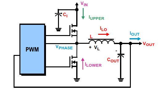
Let’s look at an example of a non-isolated buck regulator. All of the components for the non-isolated buck regulator design in Figure 2 should be carefully selected to meet the design requirements.
Calculating the inductor value is most critical in designing a step-down switching converter. First, assume the converter is in continuous conduction mode (CCM), which is usually the case. CCM implies that the inductor does not fully discharge during the switch-off time. Peak current through the inductor determines the inductor's required saturation-current rating, which in turn dictates the approximate size of the inductor.
Figure 1: Discrete Power Supply Block Diagram
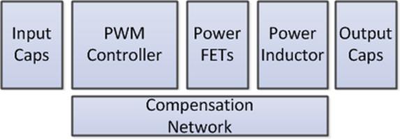
Figure 2: Basics of a Synchronous Buck Converter
Saturating the inductor core decreases the converter efficiency, while increasing the temperatures of the inductor, the MOSFET and the diode.
The output capacitor selection is also a critical part of the design. The output capacitance determines the load transient performance of the power supply. Output capacitance is required to minimize the voltage overshoot and ripple present at the output of a step-down converter. Poor load transient performance or instability is caused by insufficient output capacitance, and large voltage ripple is caused by insufficient capacitance as well as a high equivalent-series resistance (ESR) in the output capacitor. The maximum allowed output voltage overshoot and ripple are usually specified at the time of design. Thus, to meet the ripple specification for a step-down converter circuit, you must include an output capacitor with ample capacitance and low ESR.
The input capacitor is used to suppress noise at the input of the power supply and reduce the ripple voltage seen at the input. Load current, duty cycle and switching frequency are some of the factors used to determine the magnitude of the input ripple voltage. Ceramic capacitors placed directly at the input of the regulator reduce ripple voltage amplitude. Only ceramics have the extremely low ESR that is needed to reduce the ripple voltage amplitude. These capacitors must be placed close to the regulator input pins to be effective.
Careful selection of the upper and lower MOSFETs will determine the overall efficiency of the buck converter. The on-resistance of the power MOSFETs and switching losses will affect the overall efficiency. The compensation components must be selected to ensure that the design meet the stability criteria over the required operating conditions. Placement of the external components can also affect the performance of the power supply. Designers must use an optimal layout to minimize noise and maximize system efficiency.
This entire process must be repeated for each power rail. If there are 20 point-of-load power rails in the system, the process must be repeated 20 times, which can quickly become a daunting task for a power subsystem designer.
Use of a Power Module
System designers will make tradeoffs between cost, design effort and performance when selecting a power module. For systems with 1-5 power rails, designers may opt to use a discrete regulator to save cost and meet the time to market schedule. However, as the number of power rails increases and the current rating increases, the design of the power sub-system becomes challenging and requires significantly more design effort. To meet this challenge, designers may opt to use a power module solution.
Designers will also consider the cost of ownership of a discrete design. The cost of ownership is the bill of materials (BOM) cost in addition to the power designer’s time required to design and test the design. Potential re-design changes, manufacturing and assembly costs are additional expenses for discrete designs.
Figure 3 shows how a power module can integrate many of the blocks of the discrete design shown in Figure 1. A power module integrates the PWM controller, power MOSFETs, inductor and compensation network into the package. The designer typically only needs to select the input and output capacitors to complete a design.
Renesas offers a comprehensive portfolio of digital and analog point-of-load power modules to address the needs of infrastructure systems. Renesas power modules are complete DC/DC power sub-systems as shown in Figure 3. With industry-leading power technology, these modules reduce design time, lower cost and save board space. Renesas’s optimized thermal packaging technology provides excellent thermal performance, providing high current operation and high power density without the need for an external heat sink or fan, reducing system cost.
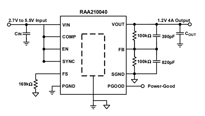
Figure 4 shows the RAA210040, Renesas’s first Mini Module with integrated inductor. The RAA210040 power module is a compact (3mmx3mmx1.7mm) synchronous step-down, non-isolated complete power supply capable of delivering up to 4A of continuous current. The RAA210040 supports a 5V and 3.3V input voltage ranges with an output range as low as 0.6V.
Figure 3: Power Module Implementation
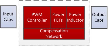
Figure 4: RAA210040 Application Circuit
Conclusion
The initial cost of implementing a discrete design may be cheaper than using a power module, but when considering time to market and long-term engineering and maintenance costs, a power module shows significant advantages, particularly for systems with 10 or more power rails. The cost of ownership, reduced design complexity, and a simplified and more flexible PCB layout are all important factors to consider.
Renesas offers a rich portfolio of digital and analog power modules to address the wide input voltage range and load current range of infrastructure systems.
Resources
Power Module Solutions
Learn more about Renesas' power module solutions
PowerNavigator Software
Simple configuration and monitoring of multiple Digital-DC devices