Features
- Buck Converter
- 4.5V to 72V input voltage
- Adjustable output voltage from 1.25V to VIN×Dmax
- 500mA output load capability
- 0.6Ω high-side MOSEFT rDS(ON)
- Fixed switching frequency 350kHz in CCM operation
- Pulse skipping mode in DCM operation
- 6V standby function by external components
- High-side OCP, UVP, UVLO, OTP fault protection
- 5V LDO Regulator
- 6V to 12V input voltage
- Fixed output voltage 5V
- 100mA output load capability
- Current limit foldback function
- 3.3V LDO Regulator
- 4.5V to 12V input voltage
- Fixed output voltage 3.3V
- 50mA output load capability
- Current limit foldback function
- SOIC8-E package
Description
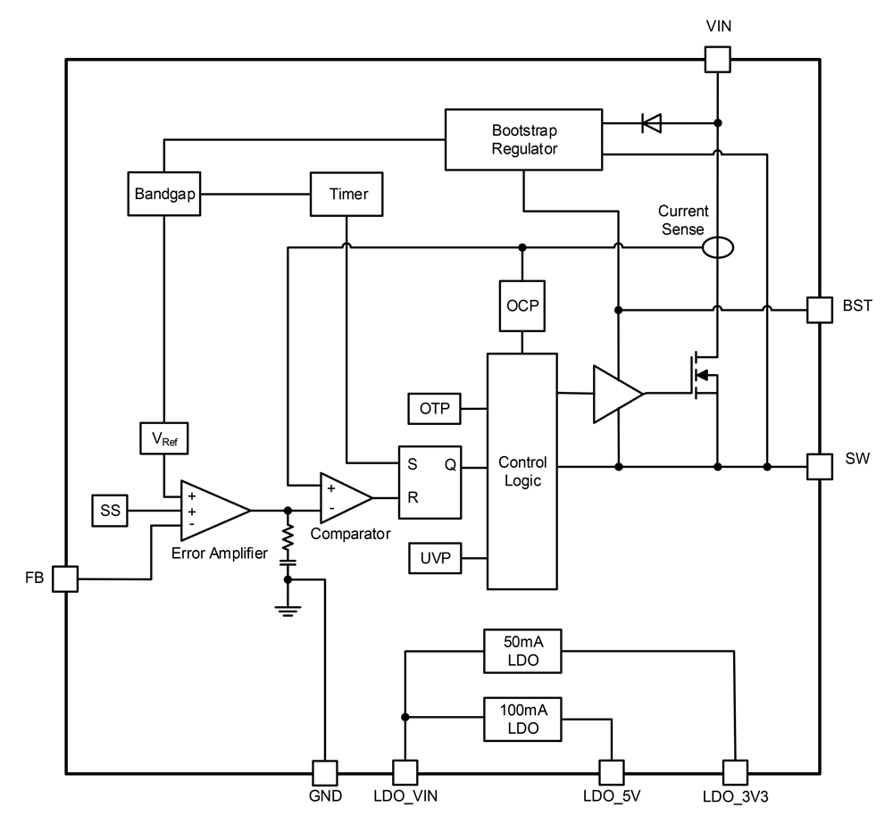
The RAA212831 is a triple output regulator combining a 4.5V to 72V input, 0.5A buck regulator with two LDO outputs. The buck regulator has a fixed switching frequency of 350kHz in Continuous Conduction mode (CCM) and operates in pulse-skipping mode at lighter loads when it enters Discontinuous Conduction mode (DCM). The two LDOs operate from a 12V (or lower) input voltage. The LDOs are rated at 100mA and 50mA of output current. The buck regulator output can be set from 1.25V to VIN×Dmax. The LDOs can support an input voltage range of 6V to 12V, and the output voltages are fixed at 3.3V and 5V. The IC is designed to provide a compact, highly integrated power management solution. Its integrated buck regulator and LDO outputs minimize system component count.
Parameters
| Attributes | Value |
|---|---|
| Topology [Rail 1] | Buck |
| Outputs (#) | 3 |
| Input Voltage (Min) [Rail 1] (V) | 4.5 |
| Input Voltage (Max) [Rail 1] (V) | 72 - 72 |
| Output Voltage (Min) [Rail 1] (V) | 1.25 |
| Output Voltage (Max) [Rail 1] (V) | 65 |
| Output Current (Max) [Rail 1] (A) | 0.5 |
| Switching Frequency Range (Typical) (kHz) | 350 - 350 |
| Control Type | Current Mode |
| Peak Efficiency (%) | 91 |
| IQ [Rail 1] (µA) | 325 |
| SYNCH Capability | No |
| Qualification Level | Standard |
| Temp. Range (°C) | -40 to +125°C |
Package Options
| Pkg. Type | Pkg. Dimensions (mm) | Lead Count (#) | Pitch (mm) |
|---|---|---|---|
| SOICN-EP | 4.9 x 3.9 x 1.40 | 8 | 1.3 |
Application Block Diagrams

|
Chainsaw System
Chainsaw system with FOC delivers high torque, reliability, and efficiency, speeding up market readiness.
|

|
Residential AFCI Circuit Breaker
AFCI circuit breaker system with Wi-Fi and AI detects arcs to prevent fires.
|

|
Active Cell Balancing Module for Low Voltage Battery Packs
Extend battery life and reduce heat with this active cell balancing module for low-voltage battery packs.
|

|
Pure Sine Wave Home Inverter with BMS
The high-performance sine wave home inverter system provides stable power, reduces costs, and ensures flexibility.
|
Additional Applications
- Electric-bike power management
- Motor driver control board power supply
Applied Filters:

