Overview
Design & Development
Software & Tools
Software & Tools
| Software title
|
Software type
|
Company
|
|---|---|---|
| HI7000/4 Real-time OS for SuperH Family μITRON4.0 Specification real-time OS for SH-1,SH-2,SH2-DSP,SH-2A,SH2A-FPU [Required IDE :High-performance Embedded Workshop]
|
ITRON OS | Renesas |
| C/C++ Compiler Package for SuperH Family C/C++ Compiler package for SuperH RISC engine Family. Simulator debugger and High-performance Embedded Workshop included.
|
Compiler/Assembler | Renesas |
| E10A-USB HS0005KCU01H for H-UDI Interface E10A-USB emulator not supporting AUD trace function.
|
Emulator | Renesas |
| E10A-USB HS0005KCU02H for AUD Trace Function E10A-USB emulator supporting AUD trace function.
|
Emulator | Renesas |
| High-performance Embedded Workshop Renesas integrated development environment (IDE) (for SuperH, RX, R8C, M32R, M16C, H8SX, H8S, H8, and 740 families).
|
IDE and Coding Tool | Renesas |
| Flash Development Toolkit (Programming GUI) Flash memory programming software. [Support MCU/MPU and devices: SuperH RISC engine, RX, R8C, M16C, H8SX, H8S, H8, 740]
|
Programmer (Unit/SW) | Renesas |
| Simulator Debugger for SuperH Family Simulator debugger for the SuperH RISC engine family [Support IDE : High-performance Embedded Workshop] (Note: This product is included in Compiler Package and is not available separately.)
|
Simulator | Renesas |
|
7 items
|
||
Sample Code
Models
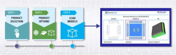
ECAD Models
Schematic symbols, PCB footprints, and 3D CAD models from SamacSys can be found by clicking on the CAD Model links in the Product Options table. If a symbol or model isn't available, it can be requested directly from SamacSys.
Product Options
Applied Filters:
Support

Support Communities
Get quick technical support online from Renesas Engineering Community technical staff.


FAQs
-
Is it OK that AVcc pins and AVss pins are in the release state?
No, it is not OK. Do not put AVcc pins and AVss pins in the release state even when converter is not used. When A/D converter is not used, set as follows; AVcc=Vcc, AVss=Vss, AVref=Vcc. If the product has AVref pins, set as follows; AVref ...
Mar 23, 2009 -
Which mode should be used to perform synchronous operation?
MTU incorporates five channel timers consisting of channel 0-4. When performing 12-phase PWM output, set channel 0, 1, and 2 to PWM mode 2 and channel 3 and 4 to PWM mode 1. The output pins at this time are as follows; channel 0 : PWM mode 2 : TIOC0A ...
Mar 24, 2009 -
How is data bus and control signal after a power-on reset in Boot mode?
The pins for the address/data bus and bus control signal are multiplexed with the input/output ports, on-chip peripheral functions and so on. In Boot mode, the following pin functions are initially selected depending on the status of the MD0 and MD1 pins. (a)MD1=0 ...
Sep 10, 2007