Overview
Description
These devices are positive-edge triggered flip-flops. The difference between HD74HCT374 and HD74HCT534 is that the former is a true outputs and the latter is a false outputs. Data at the D inputs, meeting the setup and hold time requirements, are transferred to the Q outputs on positive-going transitions of the clock (CK) input. When a high logic level is applied to the output control (OC) input, all outputs go to a high impedance state, regardless of what signals are present at the other inputs and the state of the storage elements.

Features
- LSTTL Output Logic Level Compatibility as well as CMOS Output Compatibility
- High-Speed Operation: tpd (Clock to Q) = 15ns typ (CL = 50pF)
- High Output Current: Fanout of 15 LSTTL Loads
- Wide Operating Voltage: VCC = 4.5V to 5.5V
- Low Input Current: 1µA max
- Low Quiescent Supply Current: ICC (static) = 4µA max (Ta = 25°C)
Comparison
Applications
Design & Development
Models
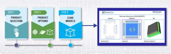
ECAD Models
Schematic symbols, PCB footprints, and 3D CAD models from SamacSys can be found by clicking on the CAD Model links in the Product Options table. If a symbol or model isn't available, it can be requested directly from SamacSys.
Support

Support Communities
Get quick technical support online from Renesas Engineering Community technical staff.

