
Developing power supplies in utility meters has been challenging. Utility meters, especially smart meters, have to operate efficiently to ensure the meters can consistently work around the clock and minimize energy consumption. With more data transmission over the cloud, security is becoming increasingly important in this market space. The RA4C1 microcontroller is designed to provide a battery backup strategy for your application, ensuring critical operation is made possible even when the main power supply fails.
To ensure low-power consumption, many low-power peripherals such as low-power timers, low-power UARTs, and a segment LCD controller are integrated into the 80MHz RA4C1 microcontroller (MCU). To reduce cybersecurity threats, an on-chip security engine, which provides isolation from the CPU for security functions and includes key management and hardware acceleration of cryptographic algorithms such as AES, ECC, and SHA, is built into the RA4C1 MCU. View the following RA4C1 block diagram for more information.
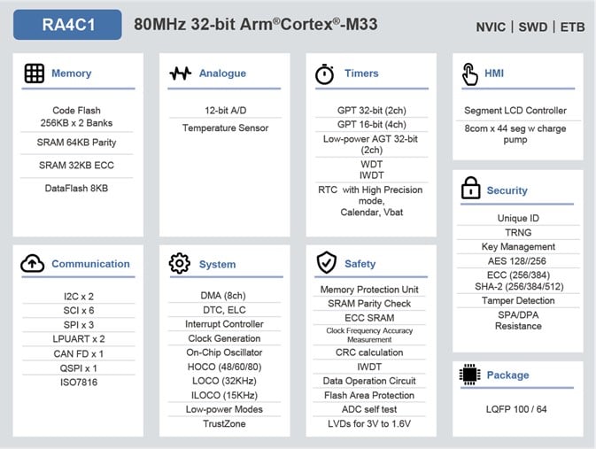
Meters need to be resilient in their operation. To enable meters to continue operating during brief outages, the RA4C1 consumes as little as 1.73µA, maintaining 16KB of SRAM, and allows the real-time clock (RTC) to consume as little as 0.38µA when operating in software standby mode. This low-power consumption feature enables users to design systems with battery backup to continue meter operation under all circumstances.
Let's look at how the RA4C1 could provide backup power during outages in the figure below. The RA4C1 has two power domains, the Vcc power domain and the RTC domain, each of which can be independently powered.
The power to the CPU, the on-chip memory, and all the peripherals, apart from the RTC, are powered by Vcc. The RTC is part of a separate power domain that is independently powered through the Vrtc pin.
With this power supply separation, the RTC can continuously operate even when the Vcc supply fails and keep accurate time using a small back-up battery connected to Vrtc. The RTC can operate on currents as little as 0.38µA while running in low consumption mode from Vrtc.
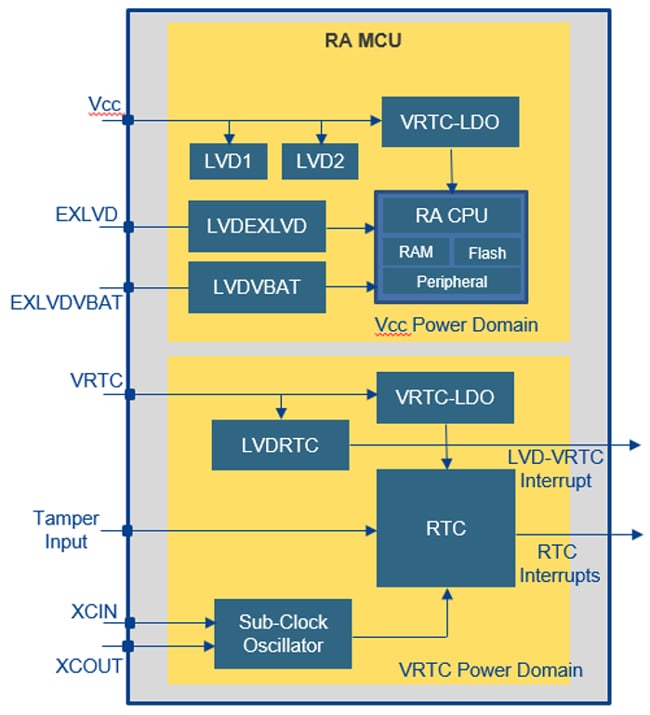
The RA4C1 also has three additional low-voltage detection inputs, which allow a user to easily manage a backup system with multiple batteries.
The EXLVD and EXLVDVBAT voltage detection circuit allows the user to monitor both the external power supply and an external backup battery, which can be used to power the whole chip when the external power fails.
The VRTC voltage detection circuit monitors the external battery voltage of the RTC back-up battery.
Each of these circuits can generate an interruption if the voltage falls below a chosen voltage level, indicating that the supply is failing.
These LVD circuits are in addition to the standard LVD circuits, LVD1 and LVD2, which monitor the internal Vcc line and can be used to give additional levels of protection.
The typical user circuit in the diagram below shows the external power supply, along with the main system back-up battery and a secondary back-up battery for the real-time clock.
In a real system, the main backup battery is a large secondary or rechargeable battery that can maintain full operation of the system for some time, and the second, smaller battery, typically a small primary battery for the RTC, is enough to maintain the time for some years.
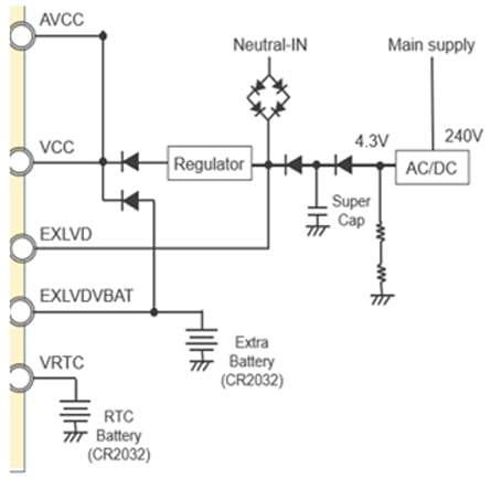
In this example system, the EXLVD circuit is used to give an advanced warning as to the failure of the external power supply. It typically takes some time after the failure of this supply before the voltage level supplied to the MCU starts to drop, so during this time, the application can respond and shut down processes safely and store any critical data into the data flash.
The system would then fall back to a backup battery supporting system operation, typically keeping critical systems alive and waiting for the power to recover.
If this battery starts to fail, the EXLVD detects the failure and the system can shut down safely, while the RTC, which is maintained by the independent backup battery, continues to operate and keep the correct time until the main power supply recovers.
This architecture enables your system to safely operate and maintain operation with an accurate clock while using one or two backup batteries. These features are ideal for many applications, such as utility meters and a wide variety of sensor applications.
Learn more about the RA4C1 MCU at www.renesas.com/ra4c1.