Features
- Ultra-high precision front-end amplifier
- Zero-drift instrumentation amplifier
- Pin selectable 9 gain settings: G = 1 to 1,000
- Rail-to-rail input/output
- Differential output
- RFI filtered inputs improve EMI rejection
- Single supply: 2.5V to 5.5V
- Dual supply: ±1.25V to ±2.75V
- Low input offset: 5μV, Maximum
- Low input offset drift: 50nV/°C, Maximum
- High CMRR: 138dB, G = 100
- Low gain error: <0.4%, All Gains, Maximum
- Gain bandwidth: 2.3MHz
- Input voltage noise (0.1Hz to 10Hz): 0.4μVP-P
- Operating temperature range: -40 °C to +125 °C
Description
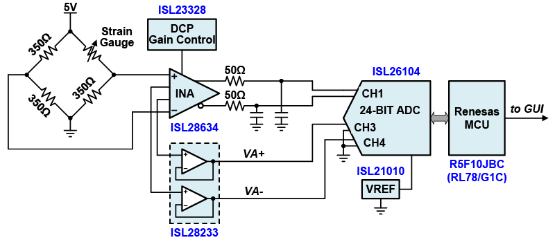
The ISL28635 is a 5V zero-drift rail-to-rail input/output (RRIO) Programmable Gain Instrumentation Amplifiers (PGIA). This instrumentation amplifier features low offset, low noise, low gain error, and high CMRR. It is ideal for high precision applications over the wide industrial temperature range. This in-amp is designed with a unique 2-bit, 3-state logic interface that allows up to 9 selectable gain settings. The ISL2863x differential output amplifier includes a reference pin to set the common-mode output voltage to interface with differential input ADCs.
Parameters
Attributes | Value |
---|---|
Channels (#) | 1 |
Bandwidth (MHz) | 2.3 |
Gain Min | 1 |
IBIAS (nA) | 0.05 |
IOUT (A) | 0.04 |
CMRR (dB) | 138 |
PSRR (db) | 140 |
Rail-to-Rail Input | Yes |
Rail-to-Rail Output | Yes |
IS per Amp (mA) | 2.9 |
Noise VN (nV/√Hz) | 400 |
Single Supply Voltage Range (V) | - |
Slew Rate (V/µs) | 0.8 |
VOUT (V) | 5.49 |
VS (Min) (V) | 2.5 |
VS (Max) (V) | 5.5 |
AVOL (dB) | 140 |
Topology [Rail 1] | VFA |
Enable | No |
Gain Error / Measurement Error (Max) | 0.05 |
Qualification Level | Standard |
Package Options
Pkg. Type | Pkg. Dimensions (mm) | Lead Count (#) | Pitch (mm) |
---|---|---|---|
TSSOP | 5.0 x 4.4 x 0.00 | 14 | 0.7 |
Applications
- Pressure and strain gauge transducers
- Weight scales
- Flow sensors
- Biometric: ECG/blood glucose
- Temperature sensors
- Test and measurement
- Data acquisition systems
- Low ohmic current sense
Applied Filters:
Filters
Software & Tools
Sample Code
Simulation Models
This video examines the use of instrumentation amplifiers (INA or in amps) for sensor applications. Intersil discusses the basics of the three-op amp INA, advantages of the zero-drift amplifiers, why use an RF input filter, monitoring sensor health, the advantages of programmable gain amplifiers and concludes with application examples for a sensor health monitor and an active shield guard drive.
Transcript
The Instrumentation Amplifier... The Circuit of Choice for Many Sensor Applications
Hello, my name is Don LaFontaine. I'm an application manager in the precision analog products group at Intersil. This video examines the use of instrumentation amplifiers (INA or in-amp) for sensor applications. Many industrial and medical applications use instrumentation amplifiers to condition small signals in the presence of large common mode voltages in DC potentials. This video will discuss the basics of the three-op amp in-amp, advantages of the zero-drift amplifiers, why would you use an RF input filter, monitoring of sensor health, and the advantages of programmable amplifier.
Three-Op Amp INA Basics
Let's first discuss the basics of the three-op amp in-amp. The high-impedance inputs of the instrumentation amplifier, coupled with the high common mode rejection, is the key to many sensor applications. The high-input impedance is achieved by using the non-inverting inputs of the input stage, without having to resort to any feedback tricks. The three-op amp circuit strips off the common mode voltage and amplifies the sensor signal with very little error. Consideration of the input common mode voltage, VCM, and the differential voltage, VD, must be taken into account to avoid saturating the input amplifiers. The saturating input stage could appear normal to the following processing circuitry and have disastrous consequences. Maximum design margin to avoid saturating the input stage can be achieved by using amplifiers with rail to rail input and output configurations.
The Three-Op Amp Instrumentation Amplifier
The following discussion gives the basic operation of the three-op amp in-amp that illustrates how the amplifier handles both common mode and differential signals. Common mode signals, VCM, is defined as the voltage common to both inputs and is the average of the sum of INA plus and INA minus. The differential voltage, VD, is defined as the net difference of INA plus and INA minus. The node voltages on the inputs of the INA, as a result of applying a common mode voltage and differential voltage, are shown. In the non-saturated mode, the op amp action of A one and two applies the differential voltage across the gain setting resistor, RG, which generates a current, ID. This results in the voltage equations as shown at VA plus and VA minus. Notice these equations. Only the differential component, VD, is amplified by the gain. While the common mode voltage, VCM, passes the input stage with unity gain and is subsequently canceled out by the common mode rejection, the amplifier A3. This action enables the in-amp to easily and effectively remove common mode signals from the desired differential signal, which is exactly what the doctor ordered. Because often times the differential signal from various sensors needs to be amplified by a hundred to a thousand times to get the sensitivity required for the measurement.
Advantages of Zero-Drift Amplifiers
The input offset voltage of all amplifiers, regardless of process technology or the architecture, will vary over temperature and time. Traditional amplifiers will spec this limit on the order of several microvolts to tens of microvolts per degree C. This offset drift can be problematic in high-precision applications. It cannot be calibrated out during initial manufacturing. In addition to drift over temperature, an amplifier's input voltage can drift over time. Zero-drift amplifiers inherently minimize both the drift over temperature and time, by continually self-correcting the offset voltage. Some zero-drift amplifiers correct the offset as much as ten thousand times a second. Zero-drift amplifiers like the ISL2853x and the ISL2863x can deliver very low offset voltage drift of 5nV/°C. Zero-drift amplifiers also eliminate 1/f noise, or flicker noise. 1/f noise is a low-frequency phenomenon caused by irregularities in the conduction path and noise due to currents within the transistors. This makes zero-drift amplifiers ideal for low-frequency input signals near DC, such as output from strain gauges, pressure sensors, thermal couples, to name a few.
RFI Input Filters
The proliferation of wireless transceivers and in portable applications has led to an increased attention to an electronic circuit's ability to operate in the vicinity of high-frequency radio transmitters such as Bluetooth. RF suppression is needed to ensure interference-free operation of the sensor. In EMI-sensitive applications, the high-frequency RF signal can appear as a rectified DC offset at the output of the precision amplifier. Because the gain of the precision front end can be 100 or greater, it's critical not to amplify any conducted or radiated noise that may be present in the amplifier's inputs. An easy solution to this problem is to include RF filters on the input of the in-amp. The ISL2853x and the ISL2863x family of in-amps have RF filters on the inputs.
Monitoring of Sensor Health
The ability to monitor any change to the sensor over time can help with robustness and accuracy of the measurement system. Direct measurements across the sensor will more than likely corrupt the readings. A solution is to use the input amplifiers of the in-amp as the impedance buffer. The ISL2853x and 2863x instrumentation amplifiers give the user access to the outputs of the input amplifiers, for just this purpose. By tying two resistors, VA plus and VA minus, the buffer input common mode voltage is extracted at the midpoints of the resistors. This voltage can be sent to an ADC sensor monitoring or feedback control, improving the precision and accuracy of the sensor over time.
Advantages of a Programmable Gain Amplifier
It is widely accepted that you cannot build a precision differential amplifier using discrete parts and get good CMRR, performance, or gain accuracy. This is due to the matching of the four external resistors used to configure the op amp in a differential amplifier. Integrated solutions have improved the matching of resistors on chip but still have the absolute matching problem to external resistors when used to set the gain of an amplifier. The tolerance between on-chip resistors values and external resistor values can typically be 20% and as high as 30%. Another source of error is the thermal performance between internal and external resistors. It is possible to have opposite temperature coefficients between the internal and the external resistors.
A programmable gain amplifier solves this problem by having all resistors on board. The gain resistors for this type of amplifier can be less than 1%, with trim capabilities on the order of 0.5% typical and plus and minus 0.4% max across temperature.
Intersil's ISL2853x and ISL2863x family of programmable in-amps offer both single-ended and differential-ended outputs with three different gain sets. Each gain set has nine different gain settings as shown. The gain sets were determined for specific applications in mind and are shown at the bottom of each column.
The ISL2853x/63xEV2Z board allows simple evaluation of the ISL2853x and ISL2863x 5V zero drift programmable gain instrumentation amplifiers. Learn how easily you can set gain of amplifier anywhere from 1 to 1000.
Transcript
This is a video for the ISL2853x and ISL2863x programmable instrumentation amplifiers. These instrumentation amplifiers feature programmable gain capability internal to the IC, and is also using zero drift amplifier technology to build these instrumentation amplifiers. Let's take a look at what's inside this instrumentation amplifier, it is built off of the three amplifier topology as I mentioned earlier, and integrates the gain resistors to this instrumentation amplifier, and uses a digital control face interface to program the gain using two digital input pins.
Another addition to this instrumentation amplifier, as you could see on the bottom is an uncommitted extra op amp which provides flexibility on this chip, this op amp is uncommitted so you can use it for any other purposes that you would like. This amplifier is for the ISL2853x family. The other part in the family is the ISL2863x and looking in this chart right here, the only thing different is we've taken what was the uncommitted amplifier in the ISL2853x family and we've integrated it into the instrumentation amplifier path, and what this gives you is basically a fully differential amplifier or you have differential inputs and a differential output. So the family of ISL2863x amplifiers are ideal for driving high precision ADD converters with differential input front ends.
As I mentioned earlier, some of the benefits of this instrumentation amplifier is the zero drift technology used to build this in amp, looking at some of the key spec advantages for this amplifier some of the highlights are very low input offset voltage of 5µV, very high precision gain accuracy in the gain set resistors that are internal to the IC, and very low noise due to the zero drift technology. The other feature as I've mentioned earlier is the programmable gain of this amplifier, using two digital inputs we have a nine gain selection state depending on the part number of the amplifier for the ISL2853x and the ISL2863x, the gain ranges can be anywhere from one to 1000.
So in this video, I'm gonna be talking about the eval board which I show right here. Everything is populated for you to easily test out this IC, the gain setting switches you see are right here. There are three state switches, so high, low, and switch open, you got your inputs to the instrumentation amplifier on your left and the outputs to the instrumentation amplifier on the right, power supply connections at the top, and for the family of the ISL2853x this is the uncommitted amplifiers for the inputs and outputs.
If you look on the back of this amplifier, the gain set table for the device is on there so that you can easily configure the switches on the front to get the gain settings that you want based on which part you're using, so that you always have them on hand that you know how to quickly set the gain of the amplifier that you need. All right, what you see here is I have the eval board powered up with a bias of plus or minus 2.5V on the power supply, I'm putting in a signal of 50mV peak-to-peak into the amplifier, and what you see here on the oscilloscope is the input signal in yellow of 50mV peak-to-peak and at the output in blue, and then I can change the gain of these switches to program the gain on the amplifier that I want to put it in.
If I change XY scale at the highest gain of... I'm using the ISL28633 so the maximum gain is a 100 for the signal, so you could see I can dynamically program the gain with the two logic inputs. So this eval board is fully populated, it's very easy to use. Some of the key applications for the ISL2853x and ISL2863x family of instrumentation amplifiers, one commonly is for bridge-type applications where you have a bridge circuit and you're trying to amplify the signal on one leg of the bridge. Most commonly these bridge circuits would be for a strain gauge or a flow sensor, and in fact, in this what you see right here is a dedicated reference design for a 24-bit strain gauge front end amplifier. If you're interested in this reference design, you can actually find more information. There is an app note written for it, it is Application Note 1853.
Another typical application for an instrumentation amplifier is high side current sensing, so in this block diagram what you see here is one of our integrated FET buck regulators the ISL8024 acting as a DC to DC power supply and this example for an FPGA or an ASIC, so you have 3.3V coming into the buck regulator and then 1.2V coming out powering the low voltage FPGA. If you want to measure the power consumption of your FPGA you can implement this solution with a high side current sense using a very low value sense resistor, in this case it's 1mOhm.
Now, 1mOhm will not give you much of a voltage drop but at 4A of load current and given the fact that these instrumentation amplifiers are built with zero drift technology that enable very, very low voltage at the input because of the low noise performance of the amplifier, you can accurately measure the current sense signal using our ISL2853x or ISL2863x instrumentation amplifiers. And in the case of resistive current sensing especially at high currents, one of the concerns is the power loss of the current sense resistor.
Well, if you're gonna use a 1mOhm sense resistor even at 4A of full load current that this ISL8024 can deliver, that is only 16mW of power dissipation within the less sensing resistor. And if you noticed earlier, I gave the noise performance of the amplifier 0.1Hz to 10Hz for low frequency this thing has 250nV peak-to-peak of input noise. Well, you can sense down to a very low range of 10mA across 1mOhm and that gives you 10µV of a DC signal that is above the noise floor of the input stage of the amplifier because this amplifier is built with zero drift technology that has very, very low noise at the input.
So to conclude the video again, here's the picture of the eval board. Everything is integrated on this board for you to easily evaluate this IC. Again, just to reiterate it's a programmable gain amplifiers of these switches will set the gain of the amp from anywhere from one to 1,000, and on the back you can find the table, how to set the resistors to set the gain of the amplifier. And then, if you need more information there is a user's guide for this eval board. Thank you very much.
Learn how the ISL28634 instrumentation amplifier is capable of being configured in high side shunt current sense amplifier. The application example includes measuring current into low voltage FPGA, DSP and ASICs.
Transcript
Hello. What you're gonna see here today is an eval board demo video for a high-side shunt current sense amplifier using one of our new products the ISL28634 instrumentation amplifier.
What you see here today in this system, is you have a power supply for the shunt load that we're gonna be measuring.
This is a DC electronic load that will actually be pulling all of the current for the load.
A DMM to measure the output of the instrumentation amplifier. The instrumentation amplifier is powered off a 5V power supply.
The shunt load is, on this board right here using an equivalent shunt of 1mOhm.
To give you a summary of what you're seeing, I have together a block diagram of the system.
We have the DC power supply. I've set it to actually 1.8V.
A DC electronic load that will be consuming all of the current.
A 1mOhm shunt resistor going into our ISL28634 instrumentation amplifier powered at single supply 5V. This instrumentation amplifier is a differential output. It has a 2.5V input reference to center the signal with your differential outputs.
Okay, so for the first thing that you see right here is I'm gonna be putting a very small current through this shunt resistor of 10mA.
And with 10mA of current going through 1mOhm, you would expect an input signal of 10µV to the amplifier. Well, this is a very small signal for any analog signal processing. So if you were to go into an MCU, you would need a very high resolution A to D to be able to measure 10µV. So, normally you would just put this amplifier into a very high gain state. Luckily, this instrumentation amplifier does have programmable gain. It has two gain switches on board where I can toggle the switches to change the gain states.
So if we look at the gain table of this instrumentation amplifier, I am using the ISL28634. And for a case of trying to measure 10mA which develops 10µV across the input, with the in-amp I'm gonna want to set a very high gain setting of 1000. So with 10µV input at a gain of 1000, I would expect 10mV of output. So here, I've set the amplifier gain already to a gain of 1000. You can see at my output, I'm measuring 13mV while sensing 10µV of input voltage off 10mA of shunt current.
Well, one could say there is an error between what's being expected and what's being actually read. Well, one thing you have to remember with any amplifier is the inherent DC VOS of the amplifier. And if you look at the data sheet for this part, you could see for the input stage the amplifier can have up to 5µV of offset. When you put this amplifier into a very high gain state at a gain of 1000, that means you can have up to plus or minus 5mV of DC offset. The output stage offset can be neglected because in a instrumentation amplifier all of the gain is present at the input stage. So, any offset at the output stage is basically overwhelmed by the gain times the input VOS of the amplifier.
So if I were to turn off this load current, you could see what the actual output offset is due to not having any input voltage. So turning off the load current as expected, you can see a DC offset of 3mV. So if you translate that back to the input, this would be 3µV of input offset. And I said earlier, that this amplifier can have up to plus or minus 5µV of offset at room temperature.
Okay. Next, let's go and put some real heavy current through this shunt resistor measurement. At the other end, I'm gonna put up to 10A of current through this shunt. And I'm gonna measure through this 1mOhm shunt resistor. And I'm gonna develop 10mV of input voltage. Since my input signal is much bigger now, I don't need such an aggressive gain otherwise I would saturate the amplifier. So, I'm gonna set the gain of this amp to 100 and I'm gonna expect a 1V output voltage.
Okay, so first, let's set this load generator to 10A of current. Okay, now you can see I'm pulling 10A of load current from my dynamic load and it's going through the shunt and it's going through the 1mOhm shunt. It's gonna develop 10mV of input voltage. Remember that my amplifier is still at a gain of 1000. That is gonna saturate the amplifier. And I wanna set it at a smaller gain. In this case, I'm gonna set it at a gain of 100.
Going back to the table for the programmable gain settings for a gain of 100, the gain setting switch states, I wanna put it in a high Z state. So I'm gonna set this back with a high Z state. And as I said earlier at 10A of current through 1mOhm shunt, I'm gonna develop 10mA of input voltage. Putting it through a gain of 100 of the instrumentation amplifier, I would expect an output voltage of about 1V. And that's what you're seeing here, with 10A of current through the shunt of 1mOhm developing 10mV putting it into a gain of 100, I'm getting 1V output.
So this little video shows you the capability of an instrumentation amplifier being configured in a high-side shunt current sense amplifier. What this application is use for is for people who want to measure current into the low voltage FPGAs, DSPs or ASICs which can consume up to 10A or 100A of current on the high end and sometimes into the 10s or 100s of milliamps at the low end. And if you want to use a very low ohmic value shunt resistor to minimize power loss in your shunt current sensing, you would need to chose an amplifier that has very low input offset and very low noise at the input. And this is what the ISL28634 that I'm using here today offers in an instrumentation amplifier in addition to the programmable gain features so that you don't need any external resistors to dynamically change the gain of the amplifier.
On this little board here just to finish up the video, it is just to give you a better look at it. This is another eval board. This is for a low-side shunt current sense amplifier using just a single amplifier and a differential configuration for low-side current sensing. This is not as accurate or some people prefer to operate in the high side and some people prefer to operate in the low side. This eval board gives you the option of operating in the low-side current sense using a single amp but this gain is fixed. So using your external resistors, you have to fix the gain. The Application Note available for this product is AN1777.
Thank you again for watching this demo video for a high-side shunt current sense amplifier using the ISL28634 instrumentation amplifier.