
In recent years, products incorporating LCD displays to enhance their value have increased, and this demand has been shifting to higher-resolution LCDs over the years. In embedded devices, there is an increasing demand not only for a small LCD like QVGA, but also for high-resolution LCDs like WVGA, and we have had many requests for using it with a general-purpose MCU.
However, there are not so many commercial MCU evaluation boards with high-resolution LDC that people cannot try easily and cannot determine if adequate performance is achieved with the general-purpose MCU. Then, I’m going to try building an evaluation environment for WVGA with commercial products. Let’s start!
I have prepared a Renesas Starter Kit+ (called RSK) with an RX72N MCU mounted and a commercial 5" WVGA LCD panel (NHD-5.0-800480TF-ATXL#-CTP).
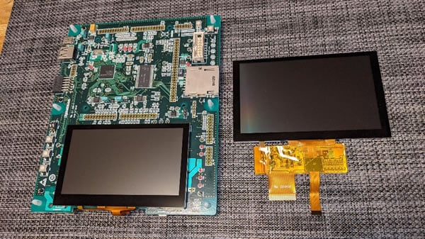
The original LCD panel mounted on the board is WQVGA, but the prepared WVGA LCD panel can also be connected as it is because both panels have the same pin position.
Release the pin lock of the flexible board and put the prepared LCD panel in, which is fixed in a standing position due to the original panel there. (Note: If you try to remove the original LCD panel forcibly, the board would be broken. So be careful!!)
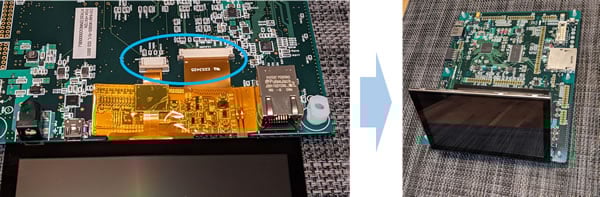
This is the end of the preparation of hardware. Let’s connect the debugger and create a GUI.
First, open the development environment e2 studio on the PC and install the GUI development assistance tool QE for Display.
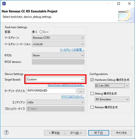
When you create a project, please be sure not to select RSK as the target board. If you chose the RSK, the original WQVGA LCD would be automatically selected. (user-friendly designs sometimes do backfires.) Confirm the heap size and the clock settings, and add the component of the GUI drawing tool ”emWin” or “Aeropoint GUI*1” in the Smart Configurator. Then, all required components are automatically imported into the project. After the settings of pins such as I2C and GLCDC, the next step is to make the settings of the graphic.
Making the settings of the panel with QE for Display. Input the LCD specifications and make settings of the color format, buffer, and so on. In this case, the 8-bit color depth is set to save the buffer capacity. For details, refer to the video and Application Note.
Create a GUI by using emWin or Aeropoint GUI*1, then the GUI is displayed like this!
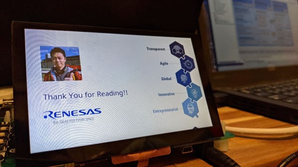
As you can see, any programming is not required so far, just replace the panel and select the settings accordingly.
After building the environment easily, you can focus on the evaluation of the GUI.
I’m not an engineer in charge of the development, but I could easily develop the GUI even with this commercial LCD panel because the development environment built the project automatically.
P.S., If you think the RSK is rather expensive, you can try combining the RX72N Envision Kit and this LCD instead.
*1 For using the Aeropoint GUI, the work RAM should be placed in external SDRAM.