About This Video
Learn how to set up the ISL28023 digital power monitor evaluation kit to measure the voltage and current performance of the ISL85415 buck regulator.
Transcript
Hello. I'm Ryan Roderick. I'm an Applications Engineer at Renesas. Today, I'm gonna demonstrate the ISL28023 made it up to an ISL85415 buck regulator.
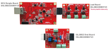
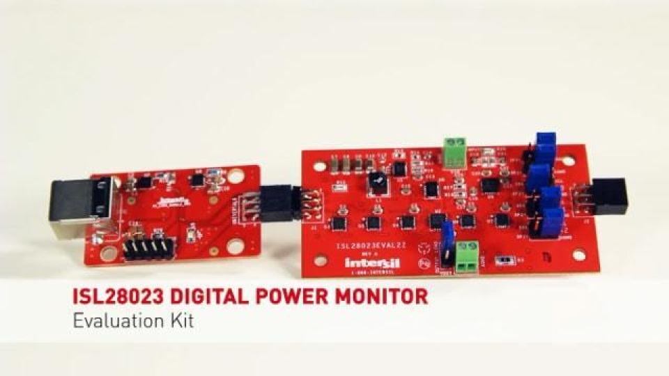
The ISL28023 is a DPM or a digital power monitor. The board I have today is part of the ISL28023's starter kit. The board measures the efficiency of the ISL85415. This is the board. This is the dongle. The dongle is basically a USB to I2C through. The Demonstration board, which is ISL28023EVAL2Z, has the ISL28023 and the ISL85415 with various loads. The ISL28023 will control the output voltage of the ISL85415 as well as measure the efficiency of the buck converter. I already have the demonstration set up. I already activated the software and I have the board connected to a one amp power supply. Make sure you use a one amp power supply, because at heavier loads with a lesser supply, lesser current source supply, the buck regulator may oscillate. Use nice short cables because any longer cables... cables have resistance so, therefore, any current flowing to the cable, there will be a voltage drop. So, nice short cables as well and if the cables are long enough, it could cause the buck regulator to oscillate.
I've launched the ISL28023/25 Evaluation Software from a Windows 7 machine. To connect the demonstration board to the computer, press Connect to Device. The software will detect what is connected to the dongle. As you could see here, is that the regular ISL28023 controls are to the left and the demonstration controls of the ISL85415 Demo board is to the right. R20 and R12, the current sense values, are the shunt resistor values that were calibrated at the factory. These were done with modest loads. If a lighter load passes through the sense resistor, the value of R shunt may decrease because the TC rating of the shunt resistor itself. R12 is the shunt resistor for the load, to measure the current to the load. These two shunt resistors will be used to calculate the efficiency of the ISL85415. To turn on the Demo board in the regulator ISL85415, press the ON button. Vbus, Vshunt, Current, Power, and Vaux will all be selected or enabled to be measured. To reduce the noise, I'll choose an Internal Avg of 128 for the Vshunt as well as the Vaux. The default state of the ISL85415 Demo board is to not have a gain resistor. Thus, the regulators may gain a one which equals the V reference value of the buck regulator, and that happens to be 600mV, as you can see here.
To set the voltage of the buck regulator to a specific voltage, press the Set Reg V button. Margin DAC, that's inside the ISL28023, dialog box will pop up. Enable the DAC Output as well as the Margin DAC. You can choose from a host of a series of ranges or half scales. I'm gonna choose the lowest range or the lowest half scale. This will provide a small step size between 0V and 0.8V. I'm gonna set the Margin DAC to be 0.16. Okay. The Vreg output will be near 3.181V. By setting the Vreg voltage, I'm enabling the gain of the V regulator. There will be an error voltage associated with the output voltage that is due to the accuracy of the V reference. If the V reference is higher, then the output voltage will be higher. If the V reference is lower than 600mV, then the reference voltage will be or the output voltage will be lower than the specified 3.181V.
3.136V has been measured at the output of the regulator. There is no load connected to the regulator at this time, so therefore, there's very little current being drawn by the regulator as well as the load. Now, I'm gonna apply the load to the regulator. You can either choose your own load by switching the output load jumper from pin 2 to 3 to pin 1 to 2 and then using the terminal to connect your own load, or you can choose the Built-In Loads to the board. I'm gonna choose maybe 11 and 7.5ohm in parallel. This puts a nice heavy load onto the regulator itself. I'm also gonna enable the efficiency measurement to be made by selecting the Efficiency check box. As you can see here, is that the efficiency of the regulator itself is around 78%. To adjust the switching frequency of the regulator, choose a switch of frequency. The default state is 900kHz. I'm gonna choose 300kHz and press the Set Frequency button. This will change the ISL23345DCP to the appropriate value such that the switching frequency is 300kHz. Press Measure Once. The efficiency has increased from 77% to 80%. The switching frequency of the ISL85415 ranges from 275kHz to 300kHz. The ISL28023 has a temperature sensor built-in inside. To enable that, press the Chip Temp check box. As one can see, is that the temperature is 35.12 degrees Centigrade. The ISL28023 is offered in a QFN package that has an EPAD slug. The EPAD slug is connected to a demo board. Currently, we have an 11ohm and a 7.5ohm in parallel, which causes the regulator to source a lot of current. In doing so, it's also heating up the ground plane as well as other components on the demo board. The EPAD is connected directly to the ground plane of the demo board. So a heating up effect of the ground plane causes the metal to heat up on the EPAD, which is reflected in the measurement that we are measuring from the internal temperature sensor. And as you can see now, since the last time I measured it, it went up 5 degrees in temperature.
Removing the load from the regulator causes less current to be sourced by the buck regulator. Less current means less heating, and after some time measuring the temperature, the temperature has decreased because there's no current on the ground plane causing the heat. There are three comparators that monitor for overvoltage, undervoltage and overcurrent connected to the primary bus channels which are the Vbus and the Vshunt. They can be accessed through the Threshold Detectors under the ISL28023 drop-down menu. Overvoltage, undervoltage and overcurrent detectors have a reference 6-bit DAC connected to each comparator. I'm going to enable the OV/OT Detector and set the range of the overvoltage and the undervoltage detector to the Vbus input to 12V. I'm gonna set the high side to 13 and then the low side to 10. Press OK. Then, there are two alert pins for the ISL28023. They can be programmed through the SMB Alert dialog box. As you can see here, is that the SMB Alert1 and SMB Alert2 share the same Digital Filter and the same comparators for overvoltage, undervoltage, and overcurrent but the SMB Alert1 is connected to an open drain and the SMB Alert 2 is a push-pull output. The SMB Alert2 is currently being used as an enable pin for the buck regulator. So, what I'm gonna do here is...I'm gonna connect the output comparator to a Digital Filter which is a glitch filter. One can choose either to glitch to last 2µS, 4µS or 8µS before it is passed to the D flip-flop which is the latch pin. We can also choose to UnMask the bit or Mask the bit. The inverter is used to determine the polarity of the active state of the error, so is it active high or is it active low. So, we'll connect to this. We'll tick that. You know, at this time, I'm gonna have the Digital Filter be...I'll choose 2µS. At this time, 2µS will be chosen for the overvoltage filter and 0µS will be chosen for the undervoltage. Okay, and now make a measurement once. As you can see here, right now our range is between 13V and 10V. I'm gonna adjust the power supply to go below 10V. And the backlight of the Vbus turns light blue, letting you know that there's an alert that has happened and it's below the undervoltage threshold.
Now I'm gonna go above the overvoltage threshold ... and I'm gonna measure again once, and you can see the backlight turns orange.
This concludes the ISL85415 and ISL28023 demonstration.