
Overview
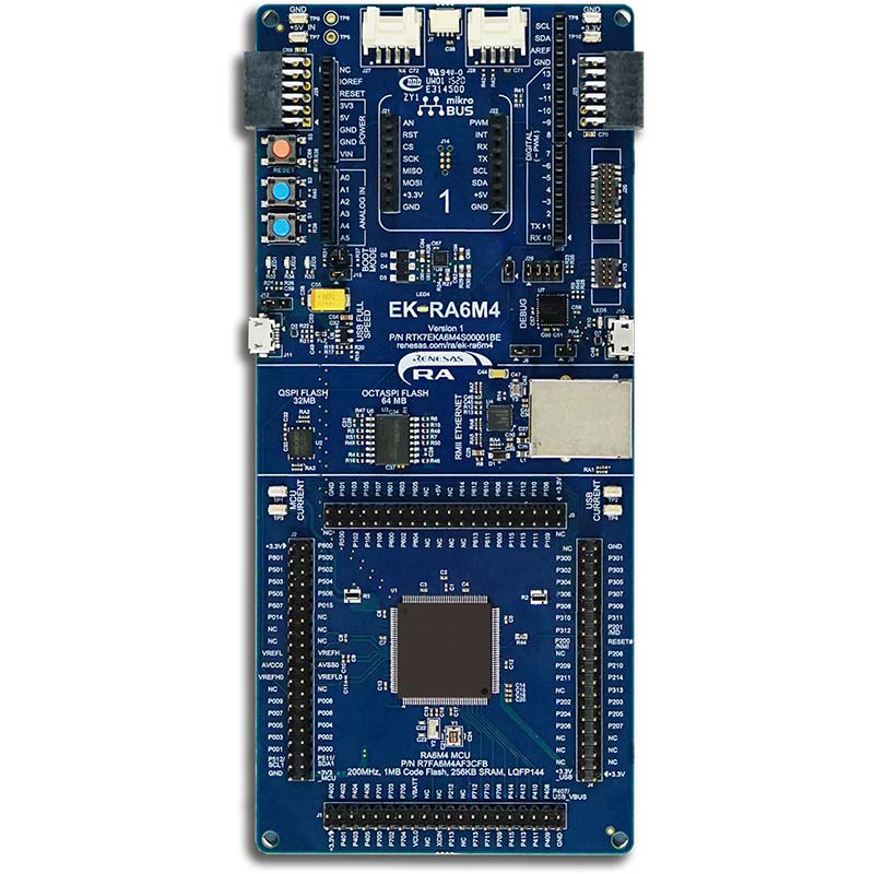
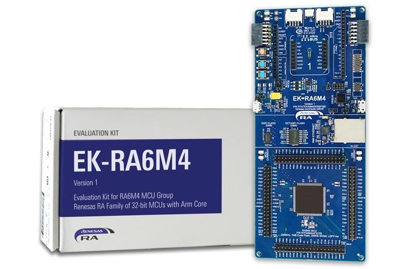
The EK-RA6M4 evaluation kit enables users to effortlessly evaluate the features of the RA6M4 MCU Group and develop embedded systems applications using the Flexible Software Package (FSP) and e2 studio IDE. Utilize rich on-board features along with your choice of popular ecosystem add-ons to bring your big ideas to life.
Getting Started
Running the Quick Start Example Project
- The EK-RA6M4 comes pre-programmed with a quick start example project (source code provided in the EK-RA6M4 Example Project Bundle (ZIP)).
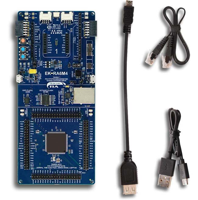
- Power up the EK-RA6M4 board through the debug USB port (J10) using the micro USB device cable connected to a 5V power source. The white power LED will light up.
- The quick start example project will begin to execute blinking the blue user LED.
- Refer to the EK-RA6M4 – Quick Start Guide (PDF | English, 日本語) to explore additional functionality of the quick start example project.
Developing Embedded Applications
- Modifying the quick start example project – refer to the EK-RA6M4 Quick Start Guide for instructions on importing, modifying, and building the quick start example project
- Start with one of the many other example projects – choose from many example projects provided in the EK-RA6M4 Example Project Bundle to learn about different peripherals of the RA6M4 MCU Group. These example projects can serve as excellent starting points for you to develop your custom applications.
Building a Custom Hardware
- Start by building a functional prototype – utilize the EK-RA6M4 board with your choice of hundreds of popular ecosystem add-ons.
- Build custom hardware – develop custom hardware by referring to the design and manufacturing information provided in the EK-RA6M4 v1 - Design Package (ZIP | English, 日本語).
Features
- Ecosystem & System Control Access:
- USB full speed host and device
- Multiple 5V input sources
- USB (debug, full speed)
- External power supply
- SEGGER J-LinkTM on-board programmer and debugger
- Debug modes:
- Debug on-board (SWD) – via J-Link
- Debug out (SWD) – via J-Link
- Debug in (ETM, SWD & JTAG) – via J-Link, Arm® Keil® ULINKTM, IAR I-jetTM, Renesas E2/E2 Lite, etc.
- User LEDs and buttons:
- Three user LEDs (red, blue, green)
- Power LED (white) indicating availability of regulated power
- Debug LED (yellow) indicating the debug connection
- Two user buttons
- One reset button
- Five most popular ecosystem expansions:
- MikroElektronikaTMmikroBUS connector
- SparkFun®Qwiic®connector
- Two SeeedGrove®system(I2C and Analog) connectors
- Two Digilent PmodTM(SPI and UART) connectors
- ArduinoTM(UNO R3) connector
- MCU boot configuration jumper
- Special Feature Access:
- Ethernet (RMII and PHY)
- 64MB External Octo-SPI Flash
- 32MB External Quad-SPI Flash
- MCU Native Pin Access:
- R7FA6M4AF3CFB MCU
- 200MHz, Arm Cortex®-M33 core
- 1MB Code Flash, 256kB SRAM
- 144 pins, LQFP package, 20mm x 20mm x 1.70mm, 0.5mm pitch
- Native pin access through 4x 40-pin male headers
- MCU and USB current measurement points
Getting Started
Test this Board Remotely with Lab on the Cloud
Explore Ready-to-Run Solutions
Sample & Buy

Evaluation Kit for RA6M4 MCU Group
| Description: | Evaluation Kit for RA6M4 MCU Group |
| HTS (US): | 8471.50.0150 |
| ECCN (US): | 3A991.a.2 |
| SPQ: | 1 |
| Pb (Lead) Free: | No |
| Assembly Location: | UNITED KINGDOM |
Add-on Hardware

Evaluation Kit for RA6M1 MCU Group

Evaluation Kit for RA6M2 MCU Group

Evaluation Kit for RA6M3 MCU Group

Evaluation Kit for RA6M5 MCU Group
IoT Targeted SPI Camera: Arducam Mega
Videos & Training
Kickstart IoT and embedded systems development using Renesas EK-RA6M4, Evaluation Kit for RA6M4 MCU Group. Familiarize yourself with the kit architecture, key features, quick start example project, and many useful resources to begin innovating quickly.
Additional Videos
News & Blog Posts
Blog Post Apr 5, 2022 |
Blog Post Jan 28, 2022 |
Blog Post Nov 18, 2021 |
Blog Post Nov 11, 2021 |
Support
Support Communities
- EK-RA6M4 Innovation Kit for RA MCU
Kickstart IoT and embedded systems development using Renesas EK-RA6M4, Evaluation Kit for RA6M4 MCU Group. Familiarize yourself with the kit architecture, key features, quick start example project and many useful resources to begin innovating quickly.
- I:002A Fundamentals of FSP (Non-Trustzone) FSP 420 EK-RA6M4
The zip file includes that materials needed to run the lab- pre-word doc, Intro Presentation and the Lab workbook.
- EK-RA6M4 and US159-DA14531EVZ Compatibility Issue
Hello Renesas Community, I'm currently working with the EK-RA6M4 evaluation kit and trying to interface it with the US159-DA14531EVZ. However, I'm having trouble getting the two boards to communicate or function together properly. Here is my previous question: Compatibility between RA0E1 Fast Prototyping Board and US159 ...
Apr 18, 2025
Knowledge Base
- Implement 3-Wire Master-Slave SPI Communication between Two Channels on EK-RA6M4
Last updated on 7th May 2026 Summary of the video This video demonstrates how to use full-duplex 3-Wire SPI with both master and slave on EK-RA6M4. FSP supports SPI on RA6M4 device with the r_spi FSP module. This example demonstrates the master sending data to the ...
- How to Implement 4-Wire SPI Communication Between Two EK-RA6M4 Channels
Last updated on 7th May 2026 Summary of the video This video demonstrates how to use full-duplex 4-Wire SPI with both master and slave on EK-RA6M4. FSP supports SPI on RA6M4 device with the r_spi FSP module. This example demonstrates the master sending data to the ...
- How to print on UART using an EK-RA6M4
Last updated on 27st April 2026 Summary of the video This video demonstrates how to use UART on EK-RA6M4. FSP supports UART communication on RA6M4 device with the r_sci_uart module. It shows how to initialize the UART peripheral and periodically transmit a message. UART (r_sci_uart ...

Support Communities

