Current Transfer Ratio (CTR)
The current transfer ratio is a parameter similar to the DC current amplification ratio of a transistor (hFE) and is expressed as a percentage indicating the ratio of the output current (IC) to the input current (IF).
CTR(%) = (IC/IF) x 100
The CTR has the following characteristics and is therefore as important as the insulation tolerance among the characteristics of a photocoupler.
- It depends on the current input to the light-emitting diode (LED) (IF)
- It is affected by the room temperature
- It changes with the operating time (age)
Sufficient care must therefore be taken with the CTR when designing; if design is not executed making enough allowance for these points, the output may be too small, causing malfunction.
Additionally, an AC (alternating current) input capable photocoupler has two LEDs (light emitting diodes) on the input side, so a CTR will also exist for each of these LEDs.
Even if IF with the same positive and negative value is input, the value of the output current IC will differ for each polarity of IF, so care must be taken on these points as well.
CTR Dependency on LED Input Current (IF)
The CTR depends on the LED input current (IF); as shown in Figure 1, the CTR decreases from a maximum point when the input current is both increased and decreased.
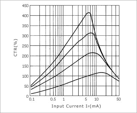
Figure 1. Example of CTR Dependency on IF
It is particularly important that the positive and negative curves of the CTR vs. input current variation slope differ between the small current area (around IF = 1mA) and the large current area (around IF = 20mA). In other words, the value of IF should be designed larger than necessary because the output current IC becomes substantially smaller as the value of IF decreases in the small current area. Conversely, in the large current area, the output current IC does not become as large as expected even if the value of IF increases, so the value of IC should be designed less than your expectation.
CTR Dependency on Temperature
Whereas the LED luminous efficiency has a negative temperature coefficient, hFE of the transistor has a positive temperature coefficient. Therefore, the CTR dependency on the temperature is a combination of these two parameters.
As shown in Figure 2, the CTR dependency on the temperature is normally realized by synthesizing the above two temperature coefficients.
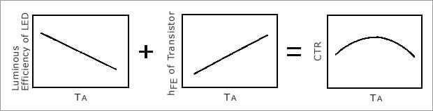
Figure 2. Mechanism of CTR Dependency on Temperature
The diagram below shows an example of an actual product.
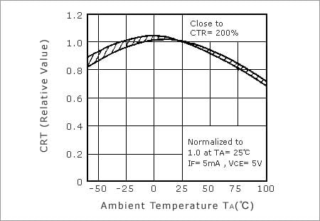
Figure 3. Example of CTR Temperature Characteristics
Change of CTR over Operating Time
The CTR of a photocoupler is based mainly on the following factors.
- The luminous efficiency of the LED
- The optical coupling efficiency between the LED and the photo-transistor
- The photo-electrical conversion efficiency and DC amplification (hFE) of the photo-transistor

Figure 4. Example of Estimated Curve of CTR Change Over Time (Typical Values)
Figure 5 shows an example of the estimated life of a photocoupler according to differences in the LED input current (IF) and the ambient temperature (TA).
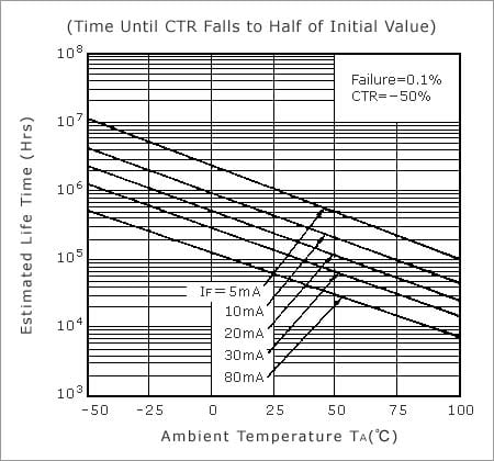
Figure 5. Example of Estimated Life of Photocoupler Based on CTR
Response Time
The response time of a photocoupler is similar to that of a transistor, and is expressed as follows.
tf // RL X hFE X CCB
RL: Load resistance, hFE: DC amplification, CCB: Capacitance between collector and base
From this formula, tf increases as the load resistance increases as shown in Figure 6, so for high-speed signal transfer, the load resistance must be designed as small as possible within the allowable rating range.
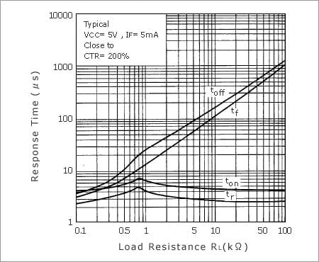
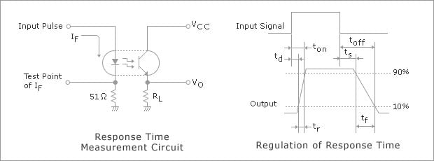
Figure 6. Response Time vs. RL Characteristics
However, when the load resistance is minimized, the transistor may not become completely ON and the output signal may be unstable unless the input current IF and output current IC are determined to be making sufficient allowance for factors such as the CTR specification range, the temperature characteristics, and the change over time.
Some examples of these characteristics are introduced below.
Figure 7 shows an example of the variation in the response time according to the ambient temperature (TA).
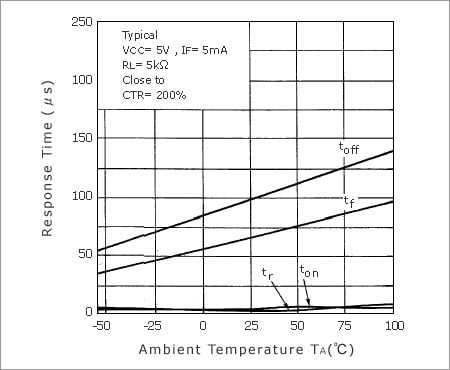
Figure 7. Response Time vs. TA Characteristics
Figure 8 shows an example of the variation in the response time according to the input current (IF).
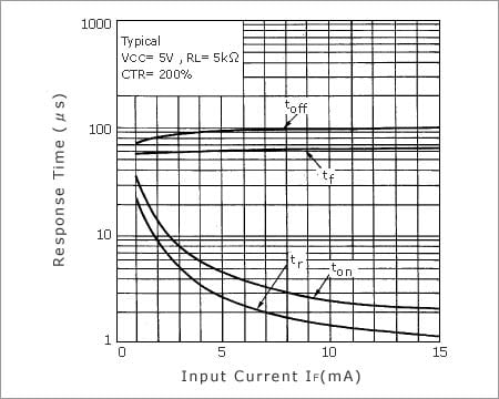
Figure 8. Response Time vs. IF Characteristics
Figure 9 shows an example of the variation in the response time according to the power supply current (VCC).
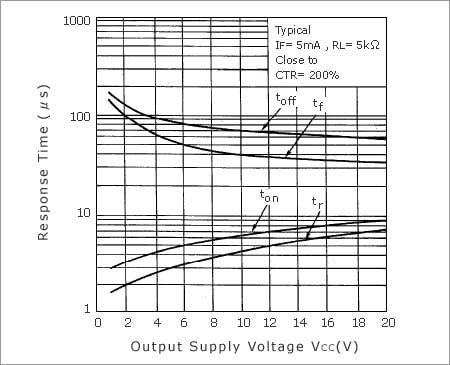
Figure 9. Response Time vs. VCC Characteristics
