In this blog, we will introduce the procedure for creating a 'Digital Angle Meter' using the RL78/G15 Fast Prototyping Board (FPB). The RL78 microcontroller provides an affordable and easy-to-use development environment. If you haven't set up the development environment yet, please refer to the blog post below for guidance.
Start Developing with the RL78 - Essential for Microcomputer Beginners - Part 1
Specifications
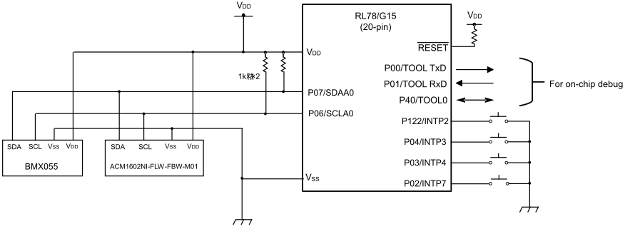
The 'Digital Angle Meter' we are creating converts angular velocity data from the gyroscope sensor (BMX055) into angles and displays it on the LCD display (ACM1602NI-FLW-FBW-M01). Both the gyroscope sensor and the LCD are controlled via I2C communication.
Below, we have posted images of the system in action.
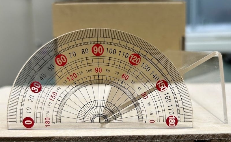
1. A slope with a 30° angle was set up. (Fig. 1)
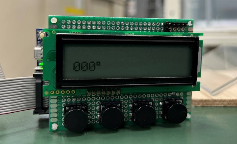
2. First, an arbitrary reference plane needs to be established. (Fig. 2)
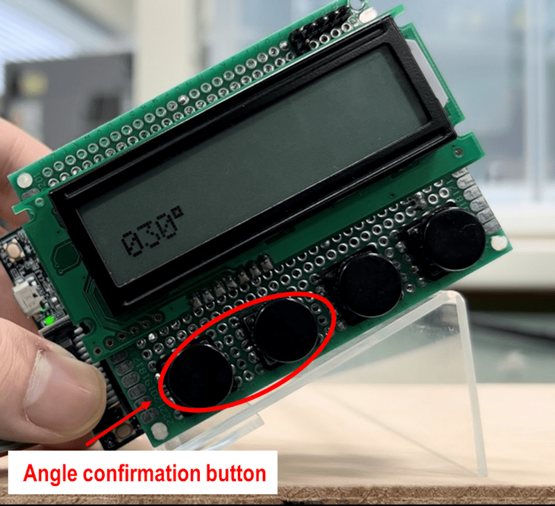
3. By tilting from there, you can measure the angle. (Fig. 3)
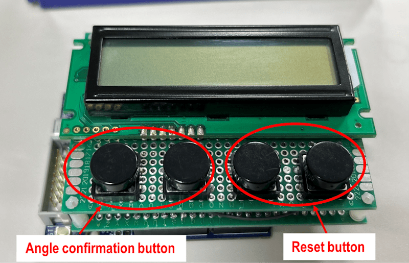
*To confirm the angle, press the 'Angle Confirmation Button'.
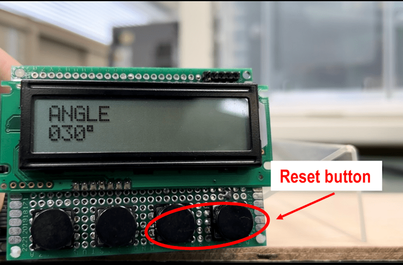
4. After the angle is confirmed, the displayed value will not change even if you move the meter. (Fig. 4)
*To measure again, press the 'Reset Button'.
Hardware Design
The following components were used in the hardware design.
- FPB (RL78/G15 20-pin)
- E2 emulator Lite
- Gyroscope sensor (BMX055)
- LCD display (ACM1602NI-FLW-FBW-M01)
- Tactile switches × 4
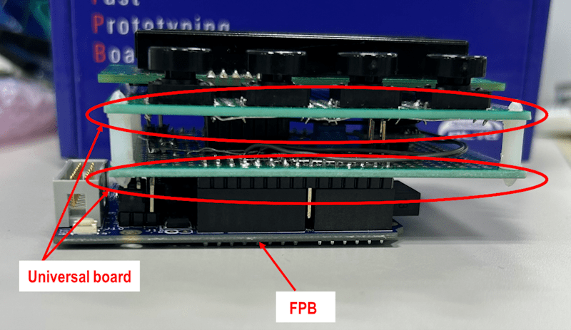
- Universal boards × 2
The following circuit was implemented on the universal board. (Fig. 5)
The completed hardware is shown below. (Fig. 6 and 7)
Software Design
Let's start by preparing the development tools to create the program. I have chosen CS+, which is beginner-friendly. Please install the development tools following the next blog post.
Integrated Development Environment Blog: Start Developing with the RL78 - Essential for Microcomputer Beginners - Part 1
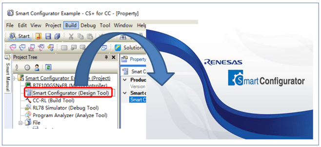
Open CS+ and click on the area highlighted in the red box in the image below (Fig. 8) to launch the code generation tool (Smart Configurator). By using Smart Configurator, you can easily generate initialization functions for various peripheral functions. Be sure to take advantage of this tool.
For instructions on how to use Smart Configurator, please refer to the user guide provided below.
User Guide: RL78 Smart Configurator User Guide: CS+ Edition
Let's now proceed to run the program that I have created.
By using the RL78 FPB, you can easily enjoy electronic projects. If you are interested in electronics, be sure to check out the related blog posts below.