概要
説明
The ZSLS7025KIT-D1 Demo Kit enables a quick and easy evaluation of ITD's ZSLS7025 Boost LED Driver within its basic application circuit and demonstrates basic layout guidelines, which are critical with any switching regulator to minimize radiated EMI. The kit includes the ZSLS7025-D1 Demo Board, which provides a standard 4-pin terminal connector to allow the user to easily connect and supply the LED board. The board also has two LED power pads (LED+ and LED-) to provide more flexibility in supplying a power LED or LED string. The board includes an external power MOSFET switch. A shielded inductor is selected to minimize radiated EMI. This reference design keeps the critical track lengths to a minimum. Ground has been maximized around critical areas.
The kit includes the ZLED-PCB10, a cascadable test PCB with 12x 300mW white HB-LEDs and selectable string length. Additional ZLED-PCB10 boards can be ordered separately.


特長
- ZLED7025PCB-D1 Demo Board
- ZLED-PCB10
- 5 samples of ZSLS7025
アプリケーション
設計・開発
関連ボード&キット
ボード&キット
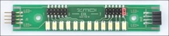
LED Test PCB - 12x 0.5W
ZLED-PCB10 is a cascadable Test PCB with 12x 0.5W white HB-LEDs and selectable string length. It is included in select IDT kits for LED driver ICs and can be ordered separately.
製品選択
| Part Number | Status | Stock | Sampleable |
|---|---|---|---|
| ZSLS7025KITD1V2P0 | Obsolete | Out of Stock | N/A |


