One of the important functions of packages is to dissipate the heat generated by the semiconductor devices they house.
Heat Generation
Heat generation affects safety, reliability, and performance.
Heat is generated when a current flows through a resistor in an electric circuit.
A semiconductor device may be regarded as a type of resistor that generates heat in proportion to the ON resistance (internal resistance when a current flows through the device) as current flows through.
Heat can adversely affect the semiconductor device itself as well as the electronic system that uses that device. In particular, it may seriously impair safety, performance, and reliability.
Excessive heat caused by a poor heat dissipation design may result in emitting smoke or catching fire, as well as degrade the performance of the device such as slowing its operating speed, and in the worst case, damaging the device or rendering it inoperable. Even if the worst case can be avoided, reliability is adversely affected through device malfunctions and a shorter system life.
To avoid these adverse effects, thermal design is essential for semiconductor packages.
Heat is released in three ways: conduction, convection, and radiation.
Heat is transferred in three ways: conduction, convection, and radiation. the image below shows how heat flows from the source (i.e. the chip) to the final destination, the atmosphere, in the context of an actual operating environment that includes printed wiring board (PWB) and an atmosphere.
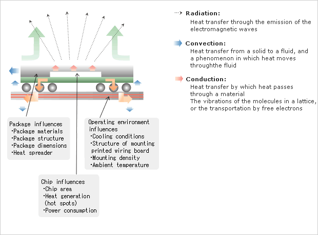
Figure 1 Heat Dissipation Paths and Causes of Thermal Resistance
Heat dissipation is done mostly through PWB.
Since heat radiation is effective only when package surface area is large enough, the following three paths shown in the diagram below are main contribution to heat dissipation.
- Convection from the top surface of the package into the atmosphere
- Conduction from the external pins/balls to PWB and then convection into the atmosphere
- Convection from the sides of the package into the atmosphere

Figure 2 Heat Flow Paths
Of these three paths, the heat dissipation path via the is the most effective and according to some calculations accounts for 80% of total heat dissipation. Actual analyses of heat dissipation indicate that 90% of the heat is released via the when a 352-pin PBGA is mounted on a 4-layer, and only 10% of the heat is dissipated from the package surface.
Thermal Resistance
Definitions of thermal resistances and thermal characteristic parameters for IC
Measuring methods and the definitions of thermal resistances are shown below based on JEDEC specifications.
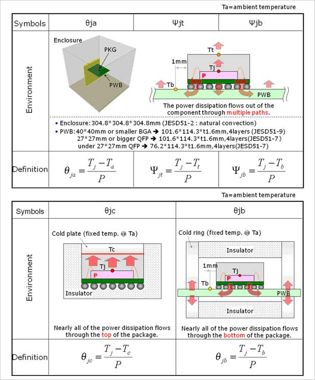
Figure 3 Definitions of Thermal Resistances and Thermal Characteristic Parameters
| θj | θja is a thermal resistance between junction temperature of a chip and ambient temperature when a package is mounted on PWB. Natural convection or forced convection will apply to the measurement conditions. θja is used to compare the thermal performance among various packages. |
|---|---|
| Ψjt, Ψjb | Ψjt is a thermal characterization parameter with respect to the total power consumption (P) of a device, indicating a temperature difference between junctions of a chip (Tj) and the center of a package top surface (Tt). Ψjb is a thermal characterization parameter with respect to the total power consumption (P) of a device, indicating a temperature difference between junctions of a chip (Tj) and the PWB close to the package (Tb). Ψjt andΨjb are used to estimate Tj from P, Tt and Tb |
| θjc, θjb | θjc is the thermal resistance between Tj and package-surface temperature (Tc) when entire heat flows from the junctions to the top package surface. θjc is mainly used in two-resister model to estimate Tj when most of the heat flows from the junctions to the top package surface. θjb is the thermal resistance between Tj and Tb when entire heat flows from the junctions to PWB. θjb is used for two-resister model. |
Reference: JEDEC JESD51
Notes:
- Thermal resistances and thermal characterization parameters significantly depend on the environment conditions.
- For that reason, JEDEC specifies the designated environment conditions to determine each thermal resistance.
- Thermal design of a system must be done based on the use conditions.
- Especially, θjc may be excessively estimated with respect to the use conditions such as heat sink capability.
Definitions of thermal resistances for discrete devices
Transient thermal resistances, in addition to steady state thermal resistances, are crucial for discrete and power devices because of their higher heat emission.
Definition of Thermal Parameters for Discrete Devices
| Symbol | Description | |
|---|---|---|
| Rated power | PT or Pch | PT or Pch is an upper limit of power applicable to a discrete device, which is mostly determined by the heat dissipation capability. |
| TC or Tc | TC of Tc is a temperature at the center point of the bottom surface of a package or at the root of the lead for Drain. *: C or c: case | |
| TA or Ta | TA or Ta is an ambient temperature *: A or a: ambient | |
| Rated temperature | Tch(max) | Tch(max) is an upper limit temperature of a channel (chip) of MOSFET. Normally it is specified to be |
| Tstg | Tstg is a permissible temperature range in storing MOSFET devices or a module or devices containing MOSFET. | |
| Transient thermal resistance | rth(t) | rth(t) is a reciprocal number of thermal conductivity of power loss to rectangular-pulse power supply. |
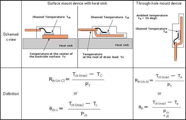
| Steady state thermal resistance | Rth(ch-C) or θch-c | Rth(ch-C) or θch-c is a thermal resistance between channels and case. |
| Rth(ch-A) or θth | Rth(ch-A) or θth is a thermal resistance between channels and ambient temperature. | |
Rth(ch-C) or Rth(ch-A) can be obtained from the absolutely maximum rating, PT and Tch(max), according to the following formula. *: symbol may vary depending on products. | ||
Figure 4 Definition of Thermal Parameters for Discrete Devices
Support

Support Communities

