Overview
Description
The Renesas Starter Kit for RX62G is intended as a user-friendly introductory and evaluation tool for the RX62G microcontroller. The board also provides a useful platform for evaluating the Renesas suite of development tools for coding and debugging, using High-performance Embedded Workshop*1 as well as programming the device using E1 emulator and/or Flash Development Toolkit. The Renesas Starter Kit for RX62G may be connected to the host PC using a simple RS232 serial connection or via the included USB E1 on chip debugging interface.
The purpose of the board is to enable the user to evaluate the capabilities of the device and its peripherals by giving the user a simple platform on which code can be run only minutes from opening box. It can also prove an invaluable tool in development by providing a useful test platform for code already debugged using one of our more powerful emulation tools.
About the bundled emulator
We have already discontinued production of the E1 emulator due to components of the product having reached their EOL (end of life, i.e. end of production). Please click on the following link to confirm the details and our successor products.
[Notification] End of Life (EOL) Notice for E1 Emulator (PDF | English, 日本語)
The Renesas Starter Kit which includes the E1 emulator is for sale as long as stocks last. There are no changes to the included emulator.
Layout and Specification
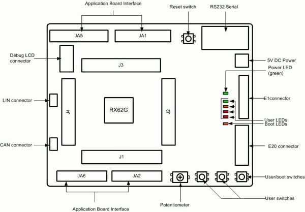
The LCD display module is supplied as a detachable sub-board. The board dimensions are 100 mm by 120 mm, detailed dimensions are available in the user manual.
| Item | Specification |
|---|---|
| Microcontroller | R5F562GAADFP |
| Input Clock | Main: 12.5 MHz |
| Potentiometer | Single-turn, 10 kΩ |
| LED | Power Indicator: green x 1 |
| Boot Indicator: orange x 1 | |
| User: green x 1, orange x 1, red x 2 | |
| Switch | Reset x 1 |
| User/Boot x 1 | |
| User x 2 | |
| DC Power Jack | 5 V Input |
| E1 Connector | 14-pin box header |
| E20 Connector | 38-pin Mictor Connector |
| RS232 Serial Connector | 9-pin DSUB |
| LCD Display Connector | 14-pin socket |
| CAN Connector | 2.54 mm pitch, 3-pin (CAN BUS line x 2, GND x 1) |
| LIN Connector | 2.54 mm pitch, 3-pin (VBAT x 1, LIN BUS line x 1, GND x 1) |
| Microcontroller Pin Header | 2.54 mm pitch, , 36-pin x 4 (J1 to J4) |
| Application Board Interface | 2.54 mm pitch, 26-pin x 2 (JA1, JA2), 24-pin x 2 (JA5, JA6) |
* E20 Connector, Microcontroller Pin Header and Application Board Interface are not contained in the product.
* The potentiometer is fitted to offer an easy way of supplying a variable analog input to the controller. It does not necessarily reflect the accuracy of the controllers ADC. Please see the device manual for details.
Manufacturer Name: PIHER INTERNATIONAL CORPORATION
Part Number: N6R (6 mm RoHS reflowable potentiometer)
Configuration
- CPU Board
- Detachable LCD Display Module
- Detachable AD Adjustment Shaft
- E1 Emulator
- Connection Cable (USB Cable, User Interface Cable)
- Quick Start Guide
- CD-ROM
- Documents: User Manual, Tutorial, and more
- IDE: High-performance Embedded Workshop
- C Compiler: C/C++ Compiler Package for RX Family Evaluation Version
- Debugger: E1/E20 Emulator Debugger
Notes
- The C/C++ Compiler Package for RX Family Evaluation Version does not come with technical support services. In addition, The C/C++ Compiler Package for RX Family Evaluation Version has some restrictions compared to the Product Version.
Trial period: 60 days
The link size will be limited to 128 KB after 60 days.
PC System Requirements
- IBM PC/AT or compatible PC (USB interface necessary) *1
- Intel Pentium Ⅲ 600 MHz or higher *3
- Memory 128 MB or higher
- Microsoft Windows 7 / Windows XP / Windows Vista *2 (other than the listed OS is not supported)
*1: IBM and PC/AT are registered trademarks of International Business Machines Corporation of the U.S.
*2: MS, MS-DOS and Windows are registered trademarks of Microsoft Corporation of the U.S. No support for Windows Vista® 64-bit editions.
*3:Pentium is a trademark of Intel Corporation of the U.S.


Applications
Documentation
|
|
|
|
|---|---|---|
| Type | Title | Date |
| Manual - Development Tools | PDF 1.83 MB 日本語 | |
| Application Note |
PDF
361 KB
日本語
AI-generated Summary:
The document explains how to manage sub-projects in CubeSuite+ by deleting unused ones from the Project Tree to streamline the build process. It details changing and setting properties of the debug tool, specifically the RX E1(JTAG), including clock frequency and supply voltage settings. Instructions cover building the project, starting the E1 emulator for program download, handling warning messages related to operating frequency, and executing the program after download completion.
|
|
| PCB Design Files | RSK RX62G Design Data
|
|
| Application Note |
PDF
81 KB
日本語
AI-generated Summary:
The sample code for the RX62G Renesas Starter Kit demonstrates peripheral initialization and ADC unit usage in one-shot mode. Source files can be accessed via the workspace in the Hi-performance Embedded Workshop. The main source file includes a detailed comment block explaining the ADC operation, which samples voltage from a potentiometer and displays results on a debug LCD. Instructions guide users to build, download, and run the code, with variable monitoring supported. Support and inquiry links are provided.
|
|
| Manual - Development Tools | PDF 67 KB | |
| Manual - Development Tools | PDF 875 KB 日本語 | |
| Manual - Development Tools | PDF 981 KB 日本語 | |
| Manual - Development Tools | PDF 579 KB 日本語 | |
8 items
|
||
Design & Development
Software & Tools
Software Downloads
|
|
|
|
|---|---|---|
| Type | Title | Date |
| Software & Tools - Evaluation Software | [Evaluation Software] Flash Development Toolkit V.4.09 Release 03
|
|
| Software & Tools - Other | Renesas Starter Kit for RX62G Installer V.1.00
|
|
| Upgrade - Debugger | RX E1/E20 Emulator debugger V.1.03.00
|
|
| Software & Tools - Evaluation Software | [Evaluation Software] RX Compiler CC-RX V.1.02 Release 01 with HEW
|
|
4 items
|
||
Sample Code
Product Options
| Part Number | Status | Stock | Description | Regional Availability | Debugger supplied |
|---|---|---|---|---|---|
| R0K50562GS000BE | Active | Out of Stock | Renesas Starter Kit for RX62G (Kit with HEW) | US, EU, CN, BR, IN, KR, SG, TW | E1 |
| R0K50562GS000BE#WS | Obsolete | Out of Stock | Renesas Starter Kit for RX62G (Kit with HEW) 有償特別出荷対応中 | JP | E1 |
Videos & Training
Additional Videos
Support

Support Communities


