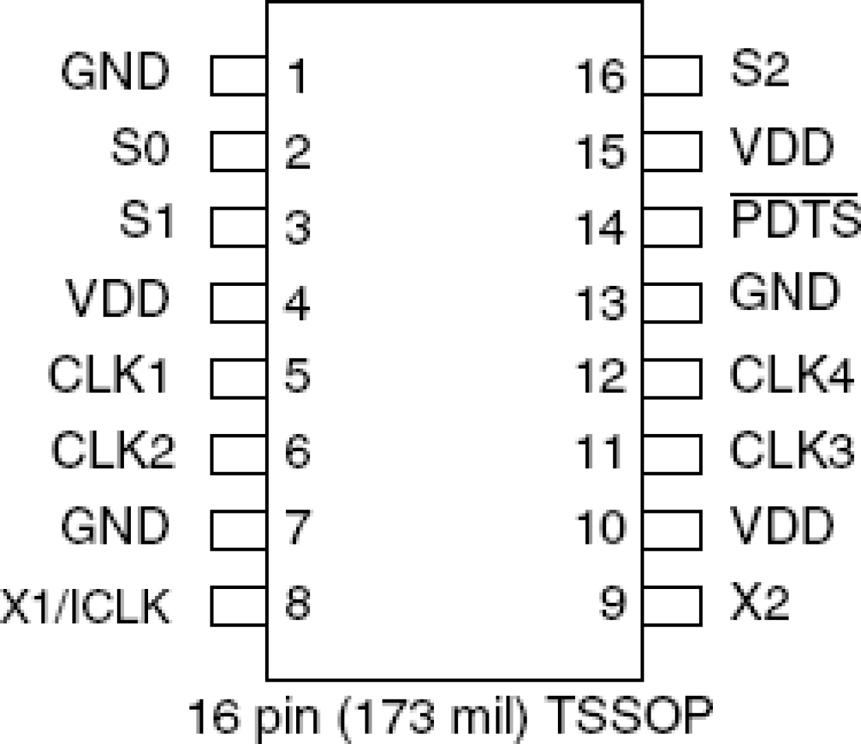
Overview

Description

The 280 field programmable spread spectrum clock synthesizer generates up to four high-quality, high-frequency clock outputs including multiple reference clocks from a low-frequency crystal input. It is designed to replace crystals, crystal oscillators and stand alone spread spectrum devices in most electronic systems. Using IDT's VersaClockTM software to configure PLLs and outputs, the 280 contains a One-Time Programmable (OTP) ROM for field programmability. Programming features include input/output frequencies, spread spectrum amount and eight selectable configuration registers. Using Phase-Locked Loop (PLL) techniques, the device runs from a standard fundamental mode, inexpensive crystal, or clock. It can replace multiple crystals and oscillators, saving board space and cost. The 280 is also available in factory programmed custom versions for high-volume applications.

Features

  • Packaged as 16-pin TSSOP – Pb-free, RoHS compliant
  • Eight addressable registers
  • Replaces multiple crystals and oscillators
  • Output frequencies up to 200 MHz at 3.3 V
  • Configurable Spread Spectrum Modulation
  • Input crystal frequency of 5 to 27 MHz
  • Input clock frequency of 3 to 166 MHz
  • Up to four reference outputs
  • Operating voltages of 3.3 V
  • Controllable output drive levels
  • Advanced, low-power CMOS process

Comparison

Applications

Documentation

Design & Development

Software & Tools

Software Downloads

Type Title Date
Software & Tools - Software Log in to Download ZIP 6.24 MB
1 item

Models

ECAD Models

Schematic symbols, PCB footprints, and 3D CAD models from SamacSys can be found by clicking on the CAD Model links in the Product Options table. If a symbol or model isn't available, it can be requested directly from SamacSys.

Diagram of ECAD Models

Product Options

Applied Filters:

Support

Support Communities

Support Communities

Get quick technical support online from Renesas Engineering Community technical staff.
Browse FAQs

FAQs

Browse our knowledge base of common questions and answers.
Submit a Ticket

Submit a Ticket

Need to ask a technical question or share confidential information?

Support Communities

  1. Unable to Flash 280KB HEX File on EK-RA8M1 – Fails with 'Failed to Erase Sectors' Error, Smaller size hex files Work Fine

    I am facing an issue while flashing a hex file of around 280KB to my Renesas EK-RA8M1 board. When the file size was around 70KB, I was able to flash it without any problems. However, with the larger file, the flashing process fails, and I get the following error ...

    Mar 28, 2025
  2. DC Motor Drive with PWM

    Hello, I am using EK-RA2E1 board and I want to drive a DC Motor with L293N Motor Driver with PWM. Is there any source that ı can inspire about this problem? Thanks for your help.

    Jun 21, 2022
  3. FCKMHZ register

    The application note on flash memory programming (https://www.renesas.com/us/en/document/apn/renesas-ra-family-flash-memory-programming?language=en) refers to a MCKMHZ register (section 2.4.18). This register sets the number of wait states used when accessing ...

    Jun 25, 2022
View All Results from Support Communities (253)

FAQs

  1. Impact on characteristics by the die thickness change

    ... is built into the front side of silicon, which is less than about 10 μm thick. Even if the overall die thickness is changed (eg. 280μm to 254μm) by the change of the back-grind, it does not affect or change the electrical characteristics of the LSI built into the ...

    Feb 13, 2023
  2. Background of the die thickness change

    ... is ground and thinned in the back-grind process. The optimal thickness of the die depends on each assembly process, package material, and other factors. For this reason, die thickness such as 280um and 254μm (=10mil) are set as standard conditions for each assembly location. Suitable Products Low Power SRAMs

    Feb 10, 2023