Overview
Description
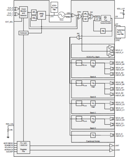
The 8V19N474 is a fully integrated FemtoClock® NG Jitter Attenuator and Clock Synthesizer designed as a high-performance clock solution for conditioning and frequency/phase management of 10/40/100/400 Gigabit-Ethernet line cards. The device is optimized to deliver excellent phase noise performance as required to drive physical layer devices and provides the clean clock frequencies of e.g. 625, 500, 312.5, 250, 156.25 and 125MHz. A two-stage PLL architecture supports both jitter attenuation and frequency multiplication. The first stage PLL is the jitter attenuator and uses an external VCXO for best possible phase noise characteristics. The second stage PLL locks on the VCXO-PLL output signal and synthesizes the target frequency. This PLL has a VCO circuit at 2500MHz.
The device generates the output clock signals from the VCO by frequency division. Five independent frequency dividers are available, four support integer-divider ratios and one integer as well as fractional-divider ratios. Delay circuits can be used for achieving alignment and controlled phase delay between clock signals. The two redundant inputs are monitored for activity. Four selectable clock switching modes are provided to handle clock input failure scenarios. Auto-lock, individually programmable output frequency dividers and phase adjustment capabilities are added for flexibility. The device is configured through an SPI interface and reports lock and signal loss status in internal registers and via an lock detect (LOCK) output. Internal status bit changes can also be reported via the nINT output. The device is ideal for driving converter circuits in wireless infrastructure, radar/imaging and instrumentation/medical applications.
For information regarding evaluation boards and material, please contact your local sales representative.
Features
- High-performance clock RF-PLL
- Optimized for low phase noise: -153dBc/Hz (1MHz offset; 156.25MHz clock)
- Integrated phase noise (12kHz-20MHz) of 75fs RMS typ.
- Dual-PLL architecture
- 1st-PLL stage with external VCXO for clock jitter attenuation
- 2nd-PLL stage with internal FemtoClock NG PLL at 2500MHz
- 6 output banks with a total of 12 outputs, organized in:
- Two clock banks with one integer frequency divider and three differential outputs
- Two clock banks with one integer frequency divider and two differential outputs
- One clock bank with one fractional output divider and one differential output
- One VCXO-PLL output bank with one selectable LVDS/two LVCMOS outputs
- Four output banks contain a phase delay circuit with steps of the VCO clock period (400ps)
- Supported clock output frequencies include:
- from the integer dividers: 2500, 1250, 625, 500, 312.5, 250, 156.25 and 125MHz
- from the fractional divider: 80 – 300MHz
- Low-power LVPECL/LVDS outputs support configurable signal amplitude, DC and AC coupling and LVPECL, LVDS line terminations techniques
- Redundant input clock architecture
- Two inputs
- Individual input signal monitor
- Digital holdover
- Manual and automatic clock selection
- Hitless switching
- Status monitoring and fault reporting
- Input signal status
- Hold-over and reference loss status
Comparison
Applications
Design & Development
Models
ECAD Models
Schematic symbols, PCB footprints, and 3D CAD models from SamacSys can be found by clicking on the CAD Model links in the Product Options table. If a symbol or model isn't available, it can be requested directly from SamacSys.

Product Options
Applied Filters:
Videos & Training
News & Blog Posts
Blog Post
Apr 27, 2021
|
News
Dec 14, 2017
|

