
Various organizations, including manufacturers, use to provide specific guidelines for the safe usage of autonomous and semi-autonomous applications. The IEC 61508, which introduced the notion of lifespan, was the very first international standard to measure the safety performance of an electrical control system. Its principal objective was to reduce the failures in all electrical, electronic, and programmable electronic safety-related systems, regardless of their usage or mode of operation.
The SIL (Safety Integrity Level) is a measure of safety system performance, in terms of the probability of failure on demand (PFD). This convention was chosen for numerical reasons since it is easier to express the probability of failure rather than the probability of proper performance. SIL is associated with four distinct integrity levels: SIL 1 to 4. The higher the SIL level, the higher the associated safety level, and the lower the likelihood of a system failing to function properly. As the SIL level rises, so do the installation and maintenance costs, as well as the system's complexity. It, also, defines SIL using requirements grouped into hardware and systematic categories. The applicable SIL is determined based on several quantitative factors in combination with qualitative factors such as the development process and safety life cycle management.
The SIL requirements for hardware safety integrity are based on a probabilistic analysis of the device. To achieve a target SIL, the device must meet targets for the maximum probability of dangerous failure and a minimum safe failure fraction. A Safety Instrumented Function (SIF) is a safety function with a specified SIL which is implemented by an SIS (safety instrumented systems) to achieve or maintain a safe state, where SIS are the systems responsible for the operating safety and ensuring the emergency stop within limits considered as safe. There are three modes of operation for a SIF: low demand mode, where the SIF is only performed on demand, to transfer the process into a specified safe state, and where the frequency of demands is no greater than one per year; high demand mode where SIF is only performed on demand, to transfer the process into a specified safe state, and where the frequency of demands is greater than one per year; and a continuous mode where the SIF retains the process in a safe state as part of normal operation. The characteristics values of the same have been provided below:
| SIL | Low demand mode: average probability of failure on demand | High demand or continuous mode: probability of dangerous failure per hour | Qualitative Consequences |
|---|---|---|---|
| 1 | ≥ 10-2 to <10-1 | ≥ 10-6 to <10-5 | Potential for minor on-site injuries |
| 2 | ≥ 10-3 to <10-2 | ≥ 10-7 to <10-6 | Potential for major on-site injuries or a fatality |
| 3 | ≥ 10-4 to <10-3 | ≥ 10-8 to <10-7 | Potential for multiple on-site fatalities |
| 4 | ≥ 10-5 to <10-4 | ≥ 10-9 to <10-8 | Potential for fatalities in the community |
Hazards of an industrial system must be identified and analyzed through risk analysis, where mitigation measures continue till the overall contribution to the hazard is considered acceptable. The tolerable level of these risks is specified as a safety requirement in the form of a target 'probability of a dangerous failure' in a given period, stated as a discrete SIL. Usually, certification schemes are used to establish whether a device meets a particular SIL. Industrial devices need to be certified for use in functional safety applications, according to IEC 61508. This requires developers to show the evidence required to demonstrate that the application, including the device, is also compliant. It should be noted that IEC 61508, the umbrella safety standard, has specific principles for the application of similar equipment for sector-specific use cases (refer to Figure 1). For example, the IEC 61511 gives requirements for the specification, design, installation, operation, and maintenance of the safety instrumented system. This standard was developed as a process sector implementation of IEC 61508.
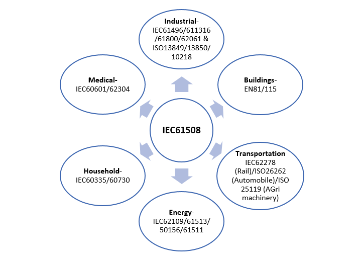
Figure 1. Industry-specific functional safety standards
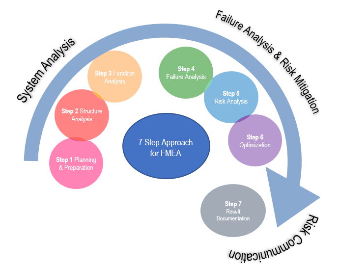
Figure 2. Approach for FMEA
The design process using an electronic device in a safety-critical system adapts the Functional Safety standard IEC 61508 and is applicable throughout the lifecycle of the systems, as its basis. The standard is broken down into 7 different parts providing full support for the implementation of SIL analysis:
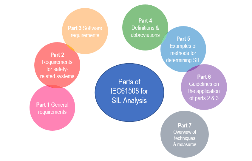
Figure 3. IEC 61508 support for SIL analysis
Broadly, SIL implemented system development proceeds in various development verification phases: the introduction/concept phase, which includes specification review; the detailed design/trial phase, which includes functional evaluation; and the main certification phase, which includes third-party inspection, verification, and certification. The whole process has technical requirements and processes that are absent in conventional non-safety system development. In addition, system development involves multi-vendor component integration. From a developer's point of view, there are a series of technical issues related to achieving a degree of SIL (refer to Figure 4). SIL-aligned functional safety systems require fault diagnosis to avoid hardware failures that can prevent the safety functions from working properly. In addition to detecting individual device failures, fault diagnosis must also detect soft-error malfunctions caused by radiation, noise, and so on during operation, and immediately shift to safe operation, such as stopping motors if an abnormality occurs. Fault diagnosis for individual devices requires analysis of each one's failure mode, an examination of fault detection methods to detect those modes, and defining the fault detection rate (diagnostic rate) based on that detection method. It is also necessary to detect soft errors using systematic functions such as monitoring program execution sequences, or inter-comparison using redundant Safety MCUs. However, with complex devices like Safety MCU, finding fault detection methods and defining their diagnostic rate pose a considerable workload for equipment developers. Furthermore, communication methods between Safety MCUs used in program sequence monitoring and inter-comparison must also be run in a way appropriate to the functional safety standards, which is another major burden for developers.
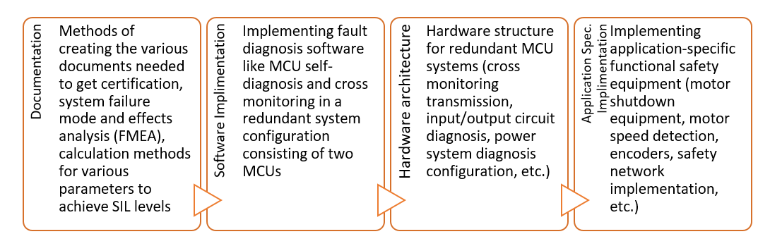
Figure 4. Technical issues for developers for attaining functional safety standards certification
Keeping the above constraints in view, Renesas' proposition for functional safety development consists of seven solutions offered by Renesas Electronics to support functional safety system development (Figure 5). The first step in developing a functional safety system is the concept phase, when specifications are reviewed, which also requires a variety of documentation. Developers without any certification experience will have to go through the process of filling out each entry and description, which is a time-consuming and costly step. The offerings provided by Renesas are iterative in nature, depending on end-user requirements.
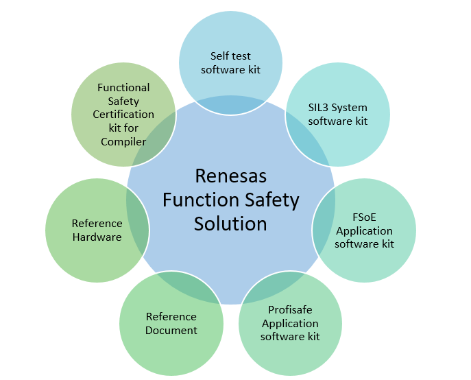
Figure 5. Renesas Functional Safety Solutions Environment
Self-Test Software Kit provides a self-diagnostic software that satisfies the SIL 3 level demanded by IEC61508 standards with a diagnostic rate of over 90%. The SIL 3 System Software Kit includes software for cross-monitoring, program sequence monitoring, and other functions required for the implementation of redundant systems, also satisfies the SIL3 requirement. Developers can use the solution as-is because it includes the primary software required for Safety MCU diagnostics, program sequence monitoring, and redundant Safety MCU cross-monitoring, and it is already SIL3 certified based on IEC61508. Using these solutions, developers can create a functional safety system by simply configuring the Self-Test Software and SIL3 System Software Kit, freeing them from tedious Safety MCU diagnostics and redundant Safety MCU control section development. Furthermore, the compilers used for this software must be demonstrated to be usable in developing functional safety systems.
Renesas also provides CC-RX, a certified IEC61508 SIL3 for the Renesas compiler. IAR Systems also offers SIL 3 compliant compilers for Renesas MCUs. The ‘Reference Documents’ from Renesas include specific examples, useful in the design and concept phase, e.g., the implementation of a safety system for a motor drive. Therefore by using such templates, the developer can easily modify them to the required specifications, so that only the necessary information is included. ‘Reference Hardware’, the hardware board, provides a range of useful information, such as power circuits for redundant Safety MCU. Another benefit of employing a redundant setup is that by exchanging processing data between each side, it is possible to verify normal functioning without needing any specialized diagnostic devices, as was shown in solution 5. It is necessary to define the hardware failure rate, diagnosis procedures, and diagnosis rate before calculating various metrics using intricate formulae based on reliability theory and demonstrating whether they satisfy the goal safety level's standard values. Reference Documents include fully finished examples of each verification document, along with thorough explanations of how each parameter was calculated and the formulas that were provided in Excel format. Even novice developers can work confidently with these tools by only adding data like failure and diagnosis rates. The reference materials explain various diagnostic procedures following various use cases since methods connected to peripheral Safety MCU functions vary depending on the use case.
Renesas' functional safety solutions, as seen in Figure 5, support the development of functional safety systems, from the concept phase to certification bodies. As a result, designers and developers can independently finish safety systems by creating device-specific components.
The dynamics of industrial automation make it clear that SIL, as defined by IEC 61508, is required on the manufacturing floor, however, it can be difficult to apply it to actual systems. Renesas makes this rather easy as it offers a number of certified software and compiler options for a wide range of MCUs across RX and RA families, verified reference boards, and the implementation guidelines for IEC61508. All of these are designed to help customers speed-up their certification process. By adopting Renesas safety packages, the developers and design engineers will only need to concentrate on their own system development, for instance, as there is no requirement for software development and certification documentation on MCU. Therefore system developers are relieved of device-specific software development and certification tasks such as Safety MCU diagnostics, resulting in more system development time, quicker SIL compliance, and above all, help lower overall cost.
Previous blog posts:
[1] Your Most Trusted Partner for Industrial Functional Safety
[2] Accelerate Functional Safety Deployment with Renesas Electronics
[3] Meet the Risk Buster: Functional Safety in Industries
[4] Introductory blog: Accelerate Your Functional Safety Design by Leveraging Renesas’ Portfolio of Certified SIL3 Solutions