概要
説明
These device are positive edge triggered flip-flops. The difference between HD74HCT374 and HD74HCT534 is only that the former is a true outputs and the latter is a false outputs. Data at the D inputs, meeting the setup and hold time requirements, are transferred to the Q outputs on positive going transitions of the clock (CK) input. When a high logic level is applied to the output control (OC) input, all outputs go to a high impedance state, regardless of what signals are present at the other inputs and the state of the storage elements.
特長
- LSTTL Output Logic Level Compatibility as well as CMOS Output Compatibility
- High-Speed Operation: tpd (Clock to Q) = 15 ns typ (CL = 50 pF)
- High Output Current: Fanout of 15 LSTTL Loads
- Wide Operating Voltage: VCC = 4.5 to 5.5 V
- Low Input Current: 1 µA max
- Low Quiescent Supply Current: ICC (static) = 4 µA max (Ta = 25°C)
製品比較
アプリケーション
設計・開発
モデル
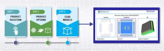
ECADモデル
SamacSysの回路図シンボル、PCBフットプリント、および3D CADモデルは、製品オプションテーブルのCADモデルリンクをクリックすることで参照できます。シンボルまたはモデルが対応していない場合は、SamacSysに直接リクエスト可能です。
製品選択
適用されたフィルター