Evaluation Kit for RA2A2 MCU Group
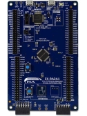
The EK-RA2A2 evaluation kit enables users to effortlessly evaluate the features of the RA2A2 MCU group and develop embedded system applications using Renesas' Flexible...
Featured Documents:
Topics
[Upgrade to Revision] Solution Toolkit QE for AFE V2.3.0: Development Assistance Tool for Analog Front End
(PDF | English, 日本語)
- Standalone version of Workflow View support
- Improved origin value setting of AFE monitor view
- Supports high-speed sampling settings (RA Family)
QE for AFE is a development assistance tool that supports the development of embedded systems that handle high-precision sensing by using MCUs that include an analog front end (AFE).
This product is available free of charge.
| Product Name | Latest Ver. | Released | Target Device | Details | Download | Operating Environment |
|---|---|---|---|---|---|---|
| QE for AFE | V2.3.0 | Jan 20, 2025 | RA Family RX Family | See Release Note | Download | Operating Environment |
Note: For detailed support devices, refer to "Target Devices".
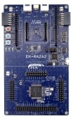
The EK-RA2A2 evaluation kit enables users to effortlessly evaluate the features of the RA2A2 MCU group and develop embedded system applications using Renesas' Flexible...
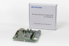
The Renesas Solution Starter Kit for RX23E-B is an evaluation tool designed for sensor measurement using the RX23E-B 32-bit microcontroller (MCU). The kit includes an...
The EK-RA2A1 evaluation kit enables users to effortlessly evaluate the features of the RA2A1 MCU Group and develop embedded systems applications using Renesas' Flexible...
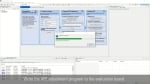
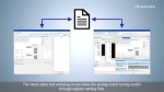
This video describes the procedure for writing the AFE adjustment program and connecting to the PC.
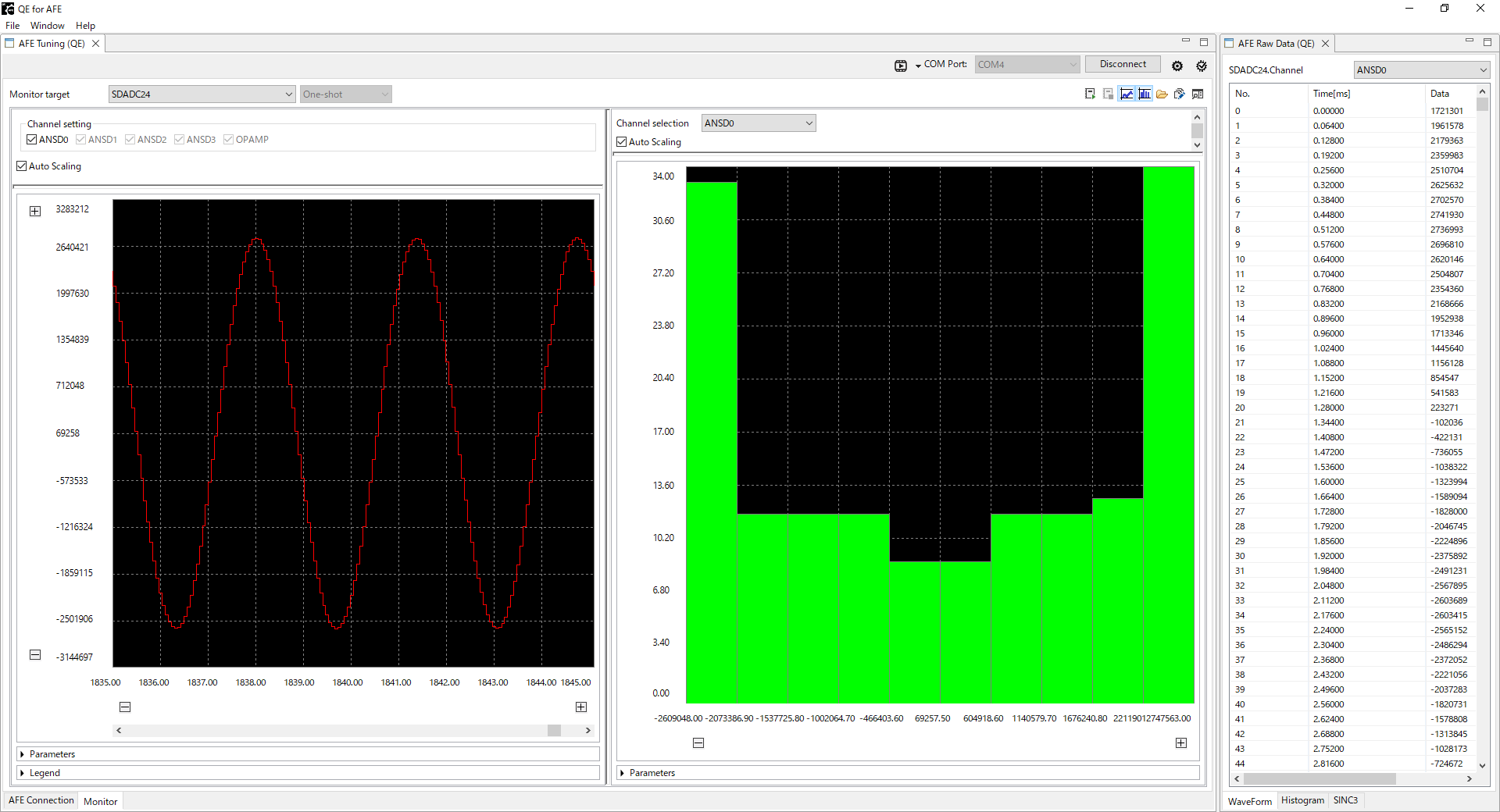
QE for AFE connects with an EK-RA2A1 board via USB serial communication to configure AFE registers on the RA2A1 MCU, check the operations, and display the A/D conversion results.
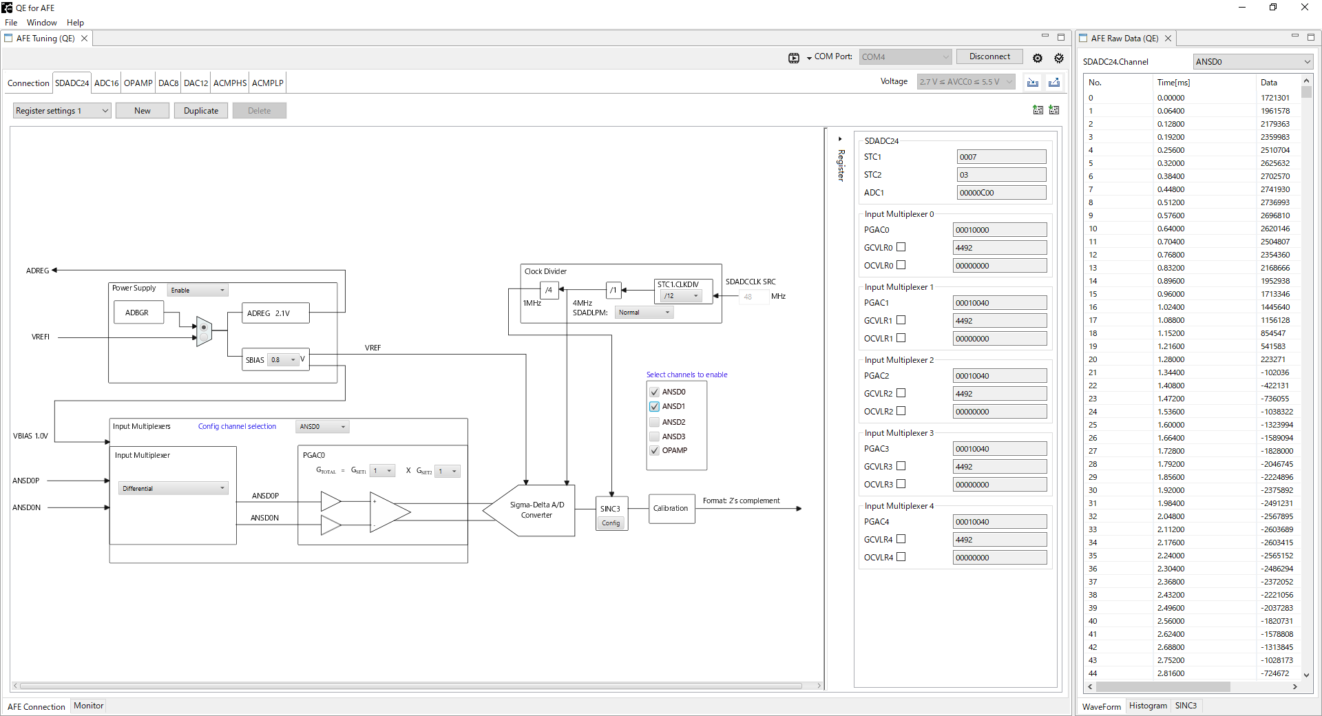
The AFE-related registers including connection with analog IPs and PGA gain settings can be configured with a graphical user interface. Through serial communication with the evaluation board via USB, you can check connection with the evaluation board, acquire and configure register values, start an A/D conversion, and acquire the A/D conversion value (A/D conversion is performed in serial scan mode).
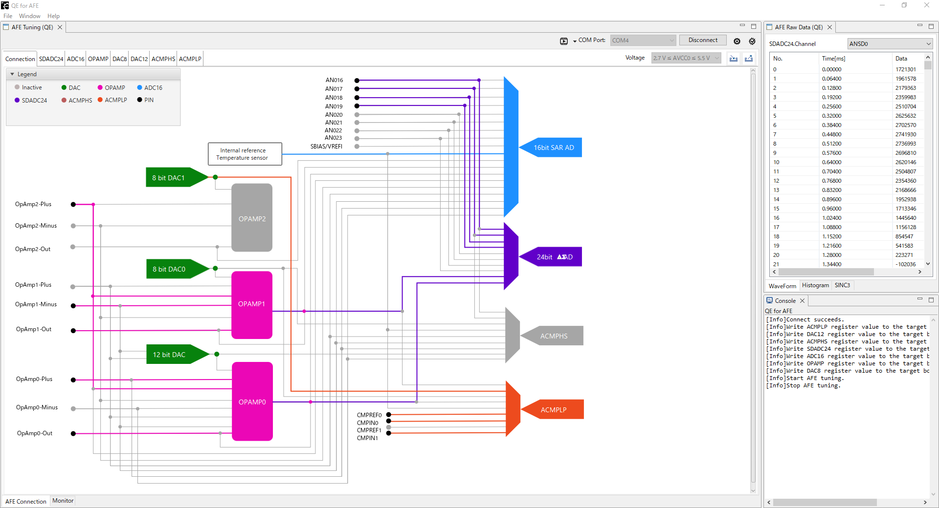
You can display a waveform and histogram and perform analysis for the acquired A/D conversion result.
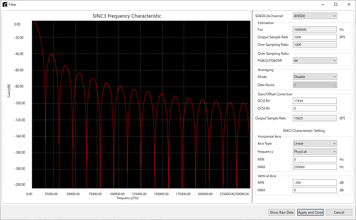
Displays the frequency-gain characteristics curve for the SINC3 filter based on register configuration values.